Supports the 9750 Family Models 9750-4i, 9750-8i, 9750-4i4e, 9750-8e, 9750-16i4e, and 9750-24i4e PN: 45412-01, Rev.
Document Description Document 45412-01, Rev. C, May 2010. This document will remain the official reference source for all revisions and releases of this product until rescinded by an update. Disclaimer It is the policy of LSI Corporation to improve products as new technology, components, software, and firmware become available. LSI reserves the right to make changes to any products herein at any time without notice.
Table of Contents About this Guide . . . . . . . . . . . . . . . . . . . . . . . . . . . . . . . . . . . . .iv Chapter 1. Getting Started . . . . . . . . . . . . . . . . . . . . . . . . . . . . . 1 Contents of this Package . . . . . . . . . . . . . . . . . . . . . . . . . . . . . . . . . . . . . . 2 9750 Controller Card Models . . . . . . . . . . . . . . . . . . . . . . . . . . . . . . . . . . . 4 Cables . . . . . . . . . . . . . . . . . . . . . . . . . . . . . . . . . . . . . . . . . . . . . . . . . . . .
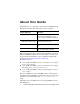
About this Guide Congratulations on your purchase of the 3ware® 9750 SATA+SAS Raid Controller Card. This guide tells you how to install it. Chapter/Appendix Description 1 Getting Started Overview of the 3ware SATA+SAS controller card and important safety factors to keep in mind during installation. 2 Installing the 9750 SATA+SAS Controller Card How to install the 3ware 9750 SATA+SAS controller card. 3 Specifications Specifications for the 9750 controller card.
Chapter 1. Getting Started The LSI 3ware 9750 SATA+SAS RAID controller card provides these features: Support for up to 127 SAS and/or SATA devices per controller, single port only. Release 10.2 adds external support. OS support includes FreeBSD, Linux, Mac OS X, OpenSolaris, VMware, and Windows. RAID 6 with simultaneous parity generation to maximize performance. LSI 2108 RAID-on-Chip (ROC) hardware platform.
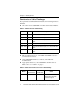
Chapter 1. Getting Started Contents of this Package If you purchased a full retail kit with cables, the following items are included: One of the 3ware 9750 RAID controller card models in Table 1. Table 1: 9750 Controller Card Family Model Ports Description 9750-4i 4 One internal 4x wide port. 9750-8i 8 Two internal 4x wide ports. 9750-4i4e 8 One internal 4x wide port, one external 4x wide port. 9750-8e 8 Two external 4x wide ports.
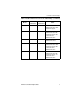
Contents of this Package Table 2: Cable and Connectors for the 9750 Family (continued) Internal Connectors External Connectors 9750-8i 2 x SFF8087 – Two internal 4 lane SATA+SAS cables with sideband support. 9750-4i4e 1 x SFF8087 1 x SFF8088 One internal 4 lane SATA+SAS cable with sideband support. One external 4 lane SATA+SAS cable. 9750-8e – 2 x SFF8088 Two external 4x lane SATA+SAS cables. 9750-16i4e 4 x SFF8087 1 x SFF8088 Four internal 4x lane SATA+SAS cables with sideband support.
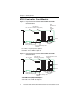
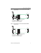
Chapter 1. Getting Started 9750 Controller Card Models Figure 1. Layout of the 4-Port 3ware 9750-4i SATA+SAS RAID Controller Card Red System Error LED CRT6A1 Heat Sink for J4L1 on back RAID-On-Chip (ROC) JT5B1 Ports 0-3 Port 0 JT3B1 JT5B3 JT6B1 JT6B3 JT5B2 JT6B2 Jumpers 85049-09 Connector for Battery Backup Unit Green Drive Activity LED CRT4B1 See jumperdescriptions descriptions SeeTable Table 76 for for jumper and Table 12 for LED descriptions and Table 11 for LED descriptions Figure 2.
750 Controller Card Models Figure 3. Layout of the 8-Port 3ware 9750-4i4e SATA+SAS RAID Controller Card J6A2 J1A4 J1A2 J1A3 J1A5 J6A3 J6A1 85062-01 J1A1 J2B2 Port 0-3 J6B1 J1B1 Port 4-7 J2B1 J6B2 CR3B2 System Error (Red LED) CR3B1 Drive Activity (Green LED) See jumper descriptions SeeTable Table 7 8 forfor jumper descriptions andTable Table 1112 for for LEDLED descriptions and descriptions Figure 4.
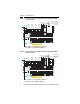
Chapter 1. Getting Started Figure 5. Layout of the 20-Port 3ware 9750-16i4e SATA+SAS RAID Controller Card J4A1 J4A3 J4A2 J5A2 J2B1 Ports 12-15 J1A2 J2B2 Ports 8-11 J3B1 Ports 4-7 J4B1 J5B3 J4B2 Ports 0-3 CRT5A1 Drive Activity (Green LED) CRT5A2 System Error (Red LED) J1L1 on back J1B1 J1B3 J1B2 Ports 16-19 J1C1 J2D1 85066-05 See Table 10 for jumper descriptions See Table 9 for jumper descriptions and Table 12 for LED descriptions and Table 11 for LED descriptions Figure 6.
Cables Cables Important: You should only use LSI 3ware certified cables with your LSI 3ware RAID controller. Using an incorrect cable can result in drives that are not detected. The appropriate cables are included with your controller. If you must replace a cable, see the list of available cables and associated part numbers at http://www.lsi.com/channel/products/ raid_controllers/accessories/cables.
Chapter 1. Getting Started System Requirements Motherboard and Slot Requirements A workstation-class or server-class motherboard with an x8 or x16 lane PCI-Express Gen 2.0 or 1.0 slot. For a list of supported motherboards, access the LSI website at http://www.lsi.com/ channel/support/marketing_resources. Click the Data & Interoperability tab. Enclosure Requirements In order to attach more than four drives per connector, enclosures with expanders are required.
System Requirements For a list of supported drives, access the LSI website at http://www.lsi.com/channel/support/marketing_resources. Click the Data & Interoperability tab.
Chapter 1. Getting Started Mozilla Firefox (current version) Safari In addition: JavaScript must be enabled Cookies must be enabled For best viewing, screen resolution should be 1024 x 768 or greater, with 16-bit color or greater. Safety Information To reduce the risk of bodily injury, electrical shock, fire, and equipment damage, read this information and observe all warnings and precautions in this guide before installing or maintaining your computer.
Safety Information Provided with a product main power disconnect or sufficient space to access the power supply cord(s), because they serve as the product's main power disconnect. Warning. We recommend you plug your system into a surge suppressor or UPS (uninterruptible power supply) and during an electrical storm, we recommend disconnecting all phone, network, and power cables. Personal Safety When Installing the 9750 Card in Your Computer Warning! High voltages may be found inside computer equipment.
Chapter 1. Getting Started Always wear a grounded strap or work on an ESD-protective mat. Do not remove the 3ware SATA+SAS controller card from its protective bag until you are properly grounded. Handle the 3ware RAID controller card by its edges or by the metal bracket. Do not touch any pin, contact, lead or component on the 3ware RAID controller card.
Safety Information Warning! PC users do NOT insert the 9750 controller card into a PCI-X slot. Doing so could potentially damage the board or the system, and void the warranty. Note: PC users some low-cost motherboards have a single PCI Express slot which is reserved for a video card. These slots cannot accommodate a 3ware 9750 SATA+SAS controller card or other PCI-E device.
Chapter 2. Installing the 9750 SATA+SAS Controller Card Chapter 2. Installing the 9750 SATA+SAS Controller Card Tools You Need You need the following tools during installation: An ESD grounding strap or mat A Phillips screwdriver Before You Start 3ware 9750 SATA+SAS controller cards can be installed in a standard enclosure or in an enclosure with a backplane. 1 Be sure to read “Safety Information” on page 10 in Chapter 1. 2 If you have a battery backup unit (BBU), install it before proceeding.
Before You Start Installing Your BBU To connect your BBU directly or remotely to your 3ware 9750 RAID controller card see: “Installing the iBBU07 Directly on the Your 3ware 9750 Controller Card” “Connecting the iBBU07 Remotely to the 3ware 9750 Controller Card” Installing the iBBU07 Directly on the Your 3ware 9750 Controller Card Follow these steps to install the iBBU07 on the SAS 9750 RAID controller. The battery backup unit is installed on the front side of the controller.
Chapter 2. Installing the 9750 SATA+SAS Controller Card 8 Use the Phillips-head screws that are provided to secure the iBBU07 to the RAID controller. 9 Install the RAID controller in a PCI Express slot in the computer. Connecting the iBBU07 Remotely to the 3ware 9750 Controller Card Use the supplied 20-pin cable to connect the iBBU07 to your RAID controller.
Installation for Mac Users Installation for Mac Users In place of the the instructions included in the section “Install the Controller in the Computer” on page 17 in this guide, follow the instructions in the user guide for your Mac Pro for opening your computer and installing a PCI Express card. If necessary, download the user guide for your Mac Pro from the Apple site and print out the chapter that includes information about opening the computer and adding PCI Express Cards.
Chapter 2. Installing the 9750 SATA+SAS Controller Card Warning! Make sure you select a PCI Express (PCI-e) slot, not a PCI or PCI-X slot, see Figure 9. Inserting a 9750 into a PCI or PCI-X slot could potentially damage the board or system, and void the warranty of either the 9750 or the motherboard. If you are uncertain about which slot to use, see the documentation for your system’s motherboard. Figure 9.
Attach the Cables to Your Controller 9 For the card to work properly, make sure the card is not slanted in any direction when you tighten the screw on the bracket to the enclosure. Attach the Cables to Your Controller Internal Connectors The 9750-8i, 9750-4i, 9750-4i4e, 9750-16i4e, and 9750-24i4e controller cards have internal connectors that use SFF-8087 cables with or without sideband support. The sidebands are necessary if you want SES enclosure management over I2C.
Chapter 2. Installing the 9750 SATA+SAS Controller Card External port J1B1 on the SAS 9750-4i4e RAID controller card. External ports J1A4 or J1B1 on the SAS 9750-8e RAID controller card. External port J1B2 on the SAS 9750-16i4e and 9750-24i4e RAID controller cards. Connect the other end of the cable to the external port on the drive enclosure. Figure 11. Mini SAS x4 Cable Plug Connector and the RAID Controller Card with External Connector Note: Figure 11 for reference only, .
Connect the Cables to Backplanes Connect the Cables to Backplanes After installing your 3ware RAID controller and making cable connections, connect the other end of the cables to an interior backplane. Internal Backplane Connection An interior connection to a backplane in the same enclosure as the RAID controller uses the SFF-8087 connector.
Chapter 2. Installing the 9750 SATA+SAS Controller Card Finishing Up the SATA+SAS Controller Card Installation After you have installed the controller in the computer and attached appropriate cables to the controller and drives, complete the following steps to complete the hardware installation. Check Installation and Close the Case 1 2 Verify that the cables do not interfere with the operation of any other components in the case or block the flow of cooling air.
Electrical Characteristics Chapter 3. Specifications Electrical Characteristics The following subsections provide the power supply requirements for the 9750 family of SATA+SAS RAID Controller Cards.
Chapter 3. Specifications 12 V is used in the charging circuitry for the optional battery pack on the optional iBBU battery-backed daughter card. If the iBBU daughter card is mounted, the following power consumption figures apply: During fast charging of the battery pack: 230 mA in the 12 V supply current. Power Supply Requirements for the 9750-24i4e and 9750-16i4e Controller Cards All power is supplied to the controller through the PCI Express 3.3 V rails and the 12 V rail.
Environmental Specification Environmental Specification The 9750 SATA+SAS RAID Controller card environmental requirements are listed in Table 5.
Chapter 3. Specifications Physical Dimensions The 9750-4i, 9750-8i, 9750-4i4e, and 9750-8e RAID controller cards have the following physical dimensions: Height: 68.91 mm (2.713 inches), Length: 167.64 mm (6.6 inches). The 9750-16i4e and 9750-24i4e high port-count RAID controller cards have the following physical dimensions: Height: 111.15 mm (4.376 inches), Length: 167.64 mm (6.6 inches). Fault Tolerance Table 6 lists the fault tolerance features for the 9750 RAID controller.
Jumper and Connector Description for the 9750 Controller Card Family Jumper and Connector Description for the 9750 Controller Card Family See Table 7 for a list of jumpers and connectors on the 9750-4i and 9750-8i RAID Controller Cards. See Figure 1 for the 9750-4i card layout. See Figure 2 for the 9750-8i card layout. Table 7: Jumpers and Connectors for 9750-4i and 9750-8i Jumper/ Connector J2B1 JT3B1 J4L1 JT5A1 Type Description Standard PCIe edge card connector x8 PCIe 2.
Chapter 3. Specifications Table 7: Jumpers and Connectors for 9750-4i and 9750-8i (continued) Jumper/ Connector JT5B1 JT5B2 Type Description 4 Lane SATA+SAS connector (Ports 0-3) SFF-8087 x4 internal mini SAS connector. UART debug connector 4-pin connector Connects the controller by cable to SATA or SAS drives, or a SAS expander. Reserved for LSI use only. JT5B3 Reserved for LSI use only 2-pin connector Jumper should not be present during normal operation.
Jumper and Connector Description for the 9750 Controller Card Family See Table 8 for a list of jumpers and connectors on the 9750-4i4e RAID Controller Card. See Figure 3 for the 9750-4i4e card layout. Table 8: Jumpers and Connectors for 9750-4i4e Jumper/ Connector J1A1 Type UART debug connector Description 4-pin connector. Reserved for LSI use. J1A2 Reserved for LSI use 2-pin connector. Jumper should not be present during normal operation. J1A3 Reserved for LSI use. 2-pin connector.
Chapter 3. Specifications Table 8: Jumpers and Connectors for 9750-4i4e (continued) Jumper/ Connector J2B1 Type Description Standard PCIe edge card connector x8 PCIe 2.0 bus connection as defined in the PCI Express specification. 4 Lane SATA+SAS connector (Ports 0-3) SFF-8087 x4 internal mini SAS connector. J6A1 Reserved for LSI use only 2-pin connector J6A2 Drive activity LED connector 2-pin connector. Writepending indicator (dirty cache) LED connector 2-pin connector.
Jumper and Connector Description for the 9750 Controller Card Family Table 8: Jumpers and Connectors for 9750-4i4e (continued) Jumper/ Connector J6B2 Type Battery backup unit connector Description 20-pin connector. Connects the optional intelligent battery backup unit (LSI iBBU07) directly to the controller. www.lsi.
Chapter 3. Specifications See Table 9 for a list of jumpers and connectors on the 9750-8e RAID Controller Card. See Figure 4 for the 9750-8e card layout. Table 9: Jumpers and Connectors for 9750-8e Jumper/ Connector Type Description J1A1 UART debug connector 4-pin connector. . Reserved for LSI use. J1A2 Reserved for LSI use. 2-pin connector. Jumper should not be present during normal operation. J1A3 Reserved for LSI use. 2-pin connector. Jumper should not be present during normal operation.
Jumper and Connector Description for the 9750 Controller Card Family Table 9: Jumpers and Connectors for 9750-8e (continued) Jumper/ Connector J6A1 Type Reserved for LSI use only Description 2-pin connector Reserved for LSI use only. J6A2 J6A3 J6B1 J6B2 Drive activity LED connector 2-pin connector. Writepending indicator (dirty cache) LED connector 2-pin connector. Remote battery backup unit (BBU) connector 20-pin connector. Battery backup unit connector 20-pin connector.
Chapter 3. Specifications See Table 10 for a list of jumpers and connectors on the 9750-16i4e RAID Controller Card. See Figure 5 for the 9750-16i4e controller card layout. Table 10: Jumpers and Connectors for 9750-16i4e Jumper/ Connector J1A2 Type Reserved for LSI use. Description 4-pin connector. Reserved for LSI use. J1B1 LED fault indication connectors for internal drive ports (Ports 8 through 15) 2x8-pin connector. There is one LED connector for each internal drive port.
Jumper and Connector Description for the 9750 Controller Card Family Table 10: Jumpers and Connectors for 9750-16i4e (continued) Jumper/ Connector J1C1 Type Reserved for LSI use. Description 3-pin connector Reserved for LSI use. J1L1 J2B1 J2B2 J2D1 J3B1 Remote battery backup unit connector 20-pin connector. 4 Lane SATA+SAS connector (Ports 12-15) SFF-8087 x4 internal mini SAS connector 4 Lane SATA+SAS connector (Ports 8-11) SFF-8087 x4 internal mini SAS connector.
Chapter 3. Specifications Table 10: Jumpers and Connectors for 9750-16i4e (continued) Jumper/ Connector J4A1 Type Description CPLD module connector 1x8-pin connector Drive activity LED connector 2-pin connector J4A3 Reserved for LSI use only 2-pin connector J4B1 LED fault indication connectors for internal drive ports (Ports 0 through 7) 2x8-pin connector. J4A2 Reserved for LSI use only.
Jumper and Connector Description for the 9750 Controller Card Family Table 10: Jumpers and Connectors for 9750-16i4e (continued) Jumper/ Connector J5A2 J5B3 Type Description Write pending LED connector 2-pin connector UART debug connector 4-pin connector Connects to an LED that indicates when the data in the cache has yet to be written to the storage devices. Used when the write-back feature is enabled. Reserved for LSI use. www.lsi.
Chapter 3. Specifications See Table 11 for a list of jumpers and connectors on the 9750-24i4e RAID Controller Card. See Figure 6 for the 9750-24i4e controller card layout. Table 11: Jumpers and Connectors for 9750-24i4e Jumper/ Connector J1A2 Type Reserved for LSI use. Description 4-pin connector. Reserved for LSI use. J1B1 LED fault indication connectors for internal drive ports (Ports 16 through 23) 2x8-pin connector. There is one LED connector for each internal drive port.
Jumper and Connector Description for the 9750 Controller Card Family Table 11: Jumpers and Connectors for 9750-24i4e (continued) Jumper/ Connector J1C1 Type Reserved for LSI use. Description 3-pin connector. Reserved for LSI use. J1L1 J2B1 J2B2 J2D1 J3B1 J4A1 Remote battery backup unit (BBU) connector 20-pin connector. 4 Lane SATA+SAS connector (Ports 20-23) SFF-8088 x4 external mini SAS connector. 4 Lane SATA+SAS connector (Ports 16-19) SFF-8087 x4 internal mini SAS connector.
Chapter 3. Specifications Table 11: Jumpers and Connectors for 9750-24i4e (continued) Jumper/ Connector J4A2 Type Description Drive activity LED connector 2-pin connector. J4A3 Reserved for LSI use only 2-pin connector J4B1 LED fault indication connectors for internal drive ports (Ports 8 through 15) 2x8-pin connector. Connects to an external LED that indicates drive activity. There is one LED connector for each internal drive port.
Jumper and Connector Description for the 9750 Controller Card Family Table 11: Jumpers and Connectors for 9750-24i4e (continued) Jumper/ Connector J5A2 J5B1 Type Description Write pending LED connector 2-pin connector. LED fault indication connectors for internal drive ports (Ports 0 through 7) 2x8-pin connector. Connects to an LED that indicates when the data in the cache has yet to be written to the storage devices. Used when the write-back feature is enabled.
Chapter 3. Specifications LEDs on 9750 Controller Card Family The 9750 family of SATA+SAS RAID controller cards have two internally surface mounted LEDs that are used as visual indicators. See Table 12 to find out what these two LEDs indicate. See Figure 1 for the location of the two LEDs (CRT4B1 green) and (CRT6A1 red) on the 9750-4i controller card. See Table 7 for list of connectors that connect to external LEDs.
Technical Certifications Technical Certifications The design and implementation of the 3ware 9750 SATA+SAS RAID controller card minimize electromagnetic emissions, susceptibility to radio frequency energy, and the effects of electrostatic discharge.
Appendix: Technical Support Appendix: Technical Support For the latest information related to 3ware RAID controllers, refer to the following world wide web sites: Product information, compatibility lists, software upgrades, and OS driver downloads, refer to: http://www.lsi.com/channel/ChannelDownloads. Select RAID Controllers from the Product Family pull-down menu and then select your applicable product, such as 3ware SAS 9750-8i. LSI KnowledgeBase at http://kb.lsi.com.