Supports the 9750-4I and 9750-8I Models PN: 45414-00, Rev.
Document Description Document 45414-00, Rev. A. November 2009. This document will remain the official reference source for all revisions and releases of this product until rescinded by an update. Disclaimer It is the policy of LSI Corporation to improve products as new technology, components, software, and firmware become available. LSI reserves the right to make changes to any products herein at any time without notice.
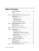
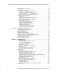
Table of Contents About this User Guide. . . . . . . . . . . . . . . . . . . . . . . . . . . . . . . . . . . . . . . viii How this User Guide is Organized . . . . . . . . . . . . . . . . . . . . . . . . . . . . . . . . . . . . . . ix Conventions . . . . . . . . . . . . . . . . . . . . . . . . . . . . . . . . . . . . . . . . . . . . . . . . . . . . . . . . x Screenshots . . . . . . . . . . . . . . . . . . . . . . . . . . . . . . . . . . . . . . . . . . . . . . . . . . . . . . . .
Browser Requirements for 3DM 2 . . . . . . . . . . . . . . . . . . . . . . . . . . . . . . . . . . . . . . . Installing 3DM . . . . . . . . . . . . . . . . . . . . . . . . . . . . . . . . . . . . . . . . . . . . . . . . . . . . . . Starting 3DM 2 and Logging In . . . . . . . . . . . . . . . . . . . . . . . . . . . . . . . . . . . . . . . . . Logging In to the 3DM 2 Web Application . . . . . . . . . . . . . . . . . . . . . . . . . . . . . Managing the 3DM 2 Daemon under Linux . . . . . . . . . . . . . . . .
Deleting a Unit through 3DM . . . . . . . . . . . . . . . . . . . . . . . . . . . . . . . . . . . . . . Deleting a Unit through 3BM . . . . . . . . . . . . . . . . . . . . . . . . . . . . . . . . . . . . . . Removing a Unit . . . . . . . . . . . . . . . . . . . . . . . . . . . . . . . . . . . . . . . . . . . . . . . . . . . Removing a Unit Through 3DM . . . . . . . . . . . . . . . . . . . . . . . . . . . . . . . . . . . . Removing a Unit Through 3BM . . . . . . . . . . . . . . . . . . . . . . . . . . . . .
Chapter 11. Enclosure Management . . . . . . . . . . . . . . . . . . . . . . . . . . . . . . . . . . . . . .190 Viewing a List of Enclosures . . . . . . . . . . . . . . . . . . . . . . . . . . . . . . . . . . . . . . . . . . Checking Enclosure Component Status . . . . . . . . . . . . . . . . . . . . . . . . . . . . . . . . . Fan Status . . . . . . . . . . . . . . . . . . . . . . . . . . . . . . . . . . . . . . . . . . . . . . . . . . . . Temp Sensor Status . . . . . . . . . . . . . . . . . . . . . . . . . .
Compliance and Conformity Statements . . . . . . . . . . . . . . . . . . . . . . . . . . . . . . . . . . .317 FCC Radio Frequency Interference Statement . . . . . . . . . . . . . . . . . . . . . . . . . . . . 317 Canadian Compliance Statement . . . . . . . . . . . . . . . . . . . . . . . . . . . . . . . . . . . . . . 318 European Community Conformity Statement . . . . . . . . . . . . . . . . . . . . . . . . . . . . . 318 Warranty, Technical Support, and Service . . . . . . . . . . . . . . . . . . . . . . .
About this User Guide This document, 3ware SATA+SAS RAID Controller Card Software User Guide, Version 10.0, provides instructions for configuring and maintaining RAID units on LSI® 3ware® 9750 series RAID controllers, using software and firmware version 10.0. This guide assumes that you have already installed your 3ware RAID controller and drives in your system and any enclosures, if you have them. If you have not yet done so, see the installation guide that came with your controller.
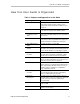
How this User Guide is Organized How this User Guide is Organized Table 1: Chapters and Appendices in this Guide Chapter/Appendix Description 1. Introduction Provides an overview of product features for the 3ware 9750 controller models. Includes system requirements and an introduction to RAID concepts and levels. 2. Getting Started Provides a summary of the process you should follow to get started using your 3ware RAID controller. 3.
Table 1: Chapters and Appendices in this Guide (Continued) Chapter/Appendix Description A. Glossary Includes definitions for terms used throughout this guide. B. Software Installation Provides instructions for installing software management tools (3DM 2 and CLI) and documentation. C. Compliance and Conformity Statements Provides compliance and conformity statement. D. Warranty, Technical Support, and Service Provides warranty information and tells you how to contact technical support.
Using the 3ware HTML Bookshelf Using the 3ware HTML Bookshelf The 3ware HTML Bookshelf is an HTML version of this user guide and the CLI Guide, combined as one resource. It is available on your 3ware CD, in the /doc/3wareHTMLBookshelf folder. To make use of the 3ware HTML Bookshelf • To launch the bookshelf at the opening page: • Navigate to the folder /doc/3wareHTMLBookshelf on the 3ware CD and double-click the file index.html.
Note: The 3ware HTML Bookshelf is created as a set of HTML documents that are often displayed from a website. When installed on your personal computer, some browsers flag them as “active content,” and require your approval before displaying the content. If you see messages similar to the following, you must confirm the display of active content in order to see the pages. xii 3ware SATA+SAS RAID Controller Card Software User Guide, Version 10.
1 Introducing the LSI 3ware SATA+SAS RAID Controller Card LSI 3ware RAID controllers deliver full-featured, true hardware RAID to servers and workstations. 3ware RAID controllers offer Serial Attached SCSI (SAS) and Serial ATA (SATA) interfaces. Combined with an advanced RAID management feature-set that includes web-based, command-based, and API (application programming interface) software components, LSI RAID controllers provide compelling RAID solutions.
Introducing the LSI 3ware SATA+SAS RAID Controller Card • Advanced Content Streaming, a performance feature, provides increased speeds for streamed data, such as video playback and editing, through improved algorithms. • Rapid RAID Recovery increases the speed with which a degraded unit can be rebuilt. It can also increase the speed of verification or initialization that may occur in the event of an unclean shutdown.
System Requirements Drive Requirements The 3ware 9750 RAID controller may be connected to up to 48 SAS and/or SATA dual-ported drives, or 96 SAS and/or SATA single-ported drives, when using one or more enclosures. A maximum of 32 drives are allowed per RAID unit and up to 32 active RAID units per controller. You cannot mix SAS and SATA drives in the same unit. Drives and drive enclosures must meet SAS (3.0 Gbps and 6.0 Gbps) and SATA (3.0 Gbps) standards.
Introducing the LSI 3ware SATA+SAS RAID Controller Card For the latest supported operating systems, see the current Release Notes at http://www.lsi.com/channel/ChannelDownloads or the file versions.txt, available on the 3ware CD. Other Requirements • Adequate air flow and cooling • Adequate power supply for drives • 3DM 2 (3ware Disk Manager) displays information in a browser. It requires one of the following browsers: • Internet Explorer 5.5 and later • Mozilla Firefox® 1.
Understanding RAID Concepts and Levels Understanding RAID Concepts and Levels 3ware RAID controllers use RAID (Redundant Array of Independent Disks) to increase your storage system’s performance and provide fault tolerance (protection against data loss).
Introducing the LSI 3ware SATA+SAS RAID Controller Card Available RAID Configurations RAID is a method of combining several hard drives into one unit. It can offer fault tolerance and higher throughput levels than a single hard drive or group of independent hard drives. LSI's 3ware controllers support RAID 0, 1, 5, 6, 10, 50, and Single Disk. The information below provides a more in-depth explanation of the different RAID levels. RAID 0 RAID 0 provides improved performance, but no fault tolerance.
Understanding RAID Concepts and Levels read performance is twice the speed of a single drive during sequential read operation. The adaptive algorithms in TwinStor technology boost performance by distinguishing between random and sequential read requests. For the sequential requests generated when accessing large files, both drives are used, with the heads simultaneously reading alternating sections of the file. For the smaller random transactions, the data is read from a single optimal drive head.
Introducing the LSI 3ware SATA+SAS RAID Controller Card RAID 6 RAID 6 provides greater redundancy and fault tolerance than RAID 5. It is similar to RAID 5, but has two blocks of parity information (P+Q) distributed across all the drives of a unit, instead of the single block of RAID 5. Due to the two parities, a RAID 6 unit can tolerate two hard drives failing simultaneously. This also means that a RAID 6 unit may be in two different states at the same time.
Understanding RAID Concepts and Levels In addition, RAID 10 arrays offer a higher degree of fault tolerance than RAID 1 and RAID 5, since the array can sustain multiple drive failures without data loss. For example, in a twelve-drive RAID 10 array, up to six drives can fail (half of each mirrored pair) and the array will continue to function. Please note that if both halves of a mirrored pair in the RAID 10 array fail, then all of the data will be lost. Figure 6.
Introducing the LSI 3ware SATA+SAS RAID Controller Card Figure 7. RAID 50 Configuration Example Single Disk A single drive can be configured as a unit through 3ware software. (3BM, 3DM 2, or CLI). Like disks in other RAID configurations, single disks contain 3ware Disk Control Block (DCB) information and are seen by the OS as available units.
Understanding RAID Concepts and Levels Determining What RAID Level to Use Your choice of which type of RAID unit (array) to create will depend on your needs. You may wish to maximize speed of access, total amount of storage, or redundant protection of data. Each type of RAID unit offers a different blend of these characteristics. The following table provides a brief summary of RAID type characteristics.
Introducing the LSI 3ware SATA+SAS RAID Controller Card Table 3: Possible Configurations Based on Number of Drives # Drives Possible RAID Configurations 5 RAID 6 RAID 5 with hot spare RAID 10 with hot spare Combination of RAID 0, RAID 1, hot spare, single disk 6 or more RAID 6 RAID 6 with hot spare RAID 50 Combination of RAID 0, 1, 5, 6,10, hot spare, single disk Using Drive Capacity Efficiently To make the most efficient use of drive capacity, it is advisable to use drives of the same capacity in a
Understanding RAID Concepts and Levels Note: All drives in a unit must be of the same type, either SAS or SATA. Support for Over 2 Terabytes Legacy operating systems such as Windows 2000, Windows XP (32-bit), Windows 2003 (32-bit and 64-bit without SP1), and Linux 2.4, do not recognize unit capacity in excess of 2 TB. If the combined capacity of the drives to be connected to a unit exceeds 2 Terabytes (TB), you can enable auto-carving when you configure your units.
Introducing the LSI 3ware SATA+SAS RAID Controller Card 3ware Tools for Configuration and Management 3ware software tools let you easily configure the drives attached to your 3ware RAID controller, specifying which drives should be used together as a RAID unit and the type of RAID configuration you want, and designating hot spares for use if a drive degrades.
Monitoring, Maintenance, and Troubleshooting Features • 3ware CLI (Command Line Interface) The 3ware CLI provides the functionality available in 3DM 2 through a Command Line Interface. You can view unit status and version information and perform maintenance functions such as adding or removing drives, and reconfiguring RAID units online. You can also use it to remotely administer controllers in a system. The 3ware CLI is described in 3ware SATA+SAS RAID Controller Card CLI Guide, Version 10.
Introducing the LSI 3ware SATA+SAS RAID Controller Card • Verification and Media Scans. The verify task verifies all redundant units, and checks for media errors on single disks, spares and RAID 0 unit members. If the disk drive is part of a redundant unit, error locations that are found and are deemed repairable are rewritten with the redundant data. This forces the drive firmware to reallocate the error sectors accordingly. (For more information, see “About Verification” on page 155.
Monitoring, Maintenance, and Troubleshooting Features checked or replaced. For more information, see “Enclosure Management” on page 190. • Auto Rebuild. For times when you do not have a spare available, setting the Auto Rebuild policy allows rebuilds to occur with an available drive or with a failed drive. (For more information, see “Setting the Auto Rebuild Policy” on page 82.) www.lsi.
2 First-Time RAID Configuration Using 3BM If you will install the operating system on and boot from a unit managed through the new 3ware RAID controller, follow the steps in this chapter to use the 3ware BIOS Manager (3BM) to configure the unit and install the driver. If the operating system is already installed on another drive in your system, you can use the steps below or you can configure units through 3DM or the CLI.
Basic Steps for Creating a Unit To launch 3BM 1 Power up or reboot your system. While the system is starting, watch for a screen similar to Figure 8. Figure 8. 3ware BIOS Screen ----Press to access 3ware BIOS Manager ---3ware ATA RAID Controller: 9750-4I BIOS: BE9X X.XX.XX.XXX Firmware: FE9X X.XX.XX.XXX BBU Status: Not Present Number of online units: 1, available drives: 0, hot spare: 0, offline units:0 Available drives: SATA - SAMSUNG HD160JJ 149.04 GB Phy 0 298.
First-Time RAID Configuration Using 3BM Figure 10. 3ware Controller Board Selection Screen You will see a screen similar to Figure 9, warning you that changing your disk array configuration may overwrite data on the disks. To select the drives and create a unit 1 Select the drives to be included by highlighting each one and pressing Enter to select it, or select all at once by selecting the heading above them.
Basic Steps for Creating a Unit 3 Make sure that the proper drives are listed. Figure 12. Create Disk Array screen To name the unit and select the desired RAID configuration 1 (Optional) Press Enter in the Array Name field and type a name for the unit. Then press Enter again to accept the name. 2 Use the arrow keys or press Tab to move to the RAID Configuration field and press Enter to display the available RAID levels for the number of drives you selected. Figure 13.
First-Time RAID Configuration Using 3BM To set other policies for the unit While creating a unit through 3BM, you can set a number of unit policies. Each of these policies is already set to a default value, so you do not have to change them. Many of these options are listed on the Create Disk Array screen. A few are available through the Advanced Options screen. 1 Use the arrow keys to move through the policies shown on the screen, select the option you want and press Enter to choose it.
Basic Steps for Creating a Unit Note: Setting a Boot Volume Size is optional. In addition, if you specify a boot volume, you do not have to install your operating system onto it. For more information about creating a boot volume, see “Boot volume size” on page 93. If the size of your array is 2TB or greater, you may also want to review the information about carving the unit into multiple volumes. For details, see “Using Auto-Carving for Multi LUN Support” on page 83. 1 Open the Advanced Options screen.
First-Time RAID Configuration Using 3BM Figure 15. Summary of Volumes to be Created To finish up and save your changes 1 If you have additional drives, you can go ahead and configure an additional RAID unit or designate a hot spare. Then continue on with these steps. (For details about hot spares, see page 26.) 2 If you configured more than one unit, and you plan to install the operating system on one of them, make that unit be the first unit (Unit 0) in the list of Exportable Units.
Basic Steps for Creating a Unit 4 Type Y to continue, delete any existing data on the drives, and create the unit. If you chose foreground initialization, then, depending on the RAID configuration you are creating, initialization of the unit may begin immediately and delay your ability to use your unit for several hours. (RAID 6 units and some RAID 5 and RAID 50 units begin immediate initialization.).
First-Time RAID Configuration Using 3BM Specifying a Hot Spare You can designate one of the Available Drives as a hot spare in 3BM. If a hot spare is specified and a redundant unit degrades, an event notification will be generated. If the hot spare is of the same type (SAS or SATA) and of adequate size, it will automatically replace the failed drive without user intervention. To specify a hot spare 1 In the list of Available Drives, highlight the drive to use.
Making Drives Visible to the Operating System Making Drives Visible to the Operating System By default, if you leave individual drives unconfigured, they will not be available to the operating system. If you want to be able to use individual drives, configure them as single-disk units. Checking the Motherboard Boot Sequence Using your computer’s BIOS setup utility, ensure that it shows the appropriate boot devices.
3 Getting Started with Your 3ware RAID Controller Setting up your 3ware RAID controller involves these main steps: • Physically Install the RAID Controller and Drives • Configure a RAID Unit • Install the Driver and Make the Operating System Aware of the New Drives • Set Up Management and Maintenance Features Once the controller and drives have been physically installed, the order in which you perform these steps depends in part on whether one of the units you configure will act as your boot drive.
installation in. Chapter 2, “First-Time RAID Configuration Using 3BM.” Additional information about configuration is also included in the later chapters of this user guide. If the operating system is already installed on another drive in your system, you can configure units through 3BM, through 3ware Disk Manager (3DM 2), or through the Command Line Interface (CLI).
Getting Started with Your 3ware RAID Controller Initial Settings for Policies and Background Tasks The table below lists the default settings for policies and background tasks. These settings are used if you do not explicitly change the policy settings.
Table 5: Default Settings for Policies and Background Tasks Policy Default Value Where to Change Background Task Settings (For details, see “Scheduling Background Tasks” on page 169 and “Setting Background Task Rate” on page 168) Verify Task Schedules Basic - Friday 12:00 am 3DM 2, 3BM, CLI Advanced - Daily, starting 3DM 2, CLI at 12:00 am and running for 24 hours Follow Verify Task Schedule Enabled - Basic schedule 3DM 2, 3BM, CLI Rebuild/Migrate Task Schedules Daily, starting at 12:00 am and r
4 Driver Installation This chapter provides details about how to install the driver for your 3ware RAID controller and make the units available to your operating system. • If the unit you have created will be your system's boot device, you install the driver for the controller as you install the operating system. • If the operating system is already installed on a unit connected to another controller or to the motherboard, you start the operating system and then install the driver.
Driver Installation Under Windows Driver Installation Under Windows Note: Before installing the 3ware driver, you may want to physically install your 3ware RAID controller in the system. Consult the installation guide that came with your controller for how to do this. If you do not have a hardcopy of the installation manual, it is available in the “doc” folder on your 3ware CD, or you can download it from the LSI website at http://www.lsi.com/channel/ChannelDownloads.
Driver Installation Creating a 3ware Driver Disk If you are installing Windows on a new unit or drive managed by the 3ware RAID controller, you can create a driver disk, or install the driver from the 3ware CD. To create a driver floppy diskette 1 Insert the 3ware CD into your Windows system. Autorun should start the 3ware menu program. If it does not, open My Computer from within the Windows Explorer, select the CD, right-click and choose AutoPlay.
Driver Installation Under Windows To install Windows 2003 and the 3ware driver 1 Boot from the Windows Server 2003 installation CD and press F6 when you see the message: “Press F6 if you need to install a 3rd party SCSI or RAID driver” at the bottom of the display. 2 When you see the message: “Setup could not determine the type of one or more mass storage devices or you have chosen to manually specify an adapter…” Type S to specify that you have an additional 3ware RAID controller.
Driver Installation 6 When the message “Select the driver to be installed” appears, choose LSI 3ware 9750 RAID Controller and click Next. 7 Continue with the normal Windows installation at this point. There are no instructions after installing the driver that are specific to 3ware. If you need additional instructions, refer to the Windows documentation supplied by Microsoft. 8 Follow the instructions under “Making Units Managed by a 3ware Controller Available to Windows” on page 38.
Driver Installation Under Windows Figure 18. 3ware Device Driver Installation Wizard 3 Click Next. You will see the following screen. The green checkmarks indicate successful installation of the driver. If unsuccessful, there will be a red checkmark. Figure 19. Final Installation Screen 4 Click Finish to exit the installer. www.lsi.
Driver Installation 5 If your 3ware RAID controller card is not yet installed, power down the system and physically install the controller card. When you turn your computer on again, Windows will automatically detect that the controller has been installed. 6 When prompted, click the default Next to have Windows automatically select the driver. The driver will automatically be detected, and the controller will be ready to use. Windows may or may not require that you reboot your computer.
Driver Installation Under Linux Driver Installation Under Linux Note: Before installing the 3ware driver, you may have already installed your 3ware RAID controller in the system. Consult the installation guide that came with your controller for how to do this. If you do not have a hardcopy of the installation manual, it is available in the “doc” folder on your 3ware CD, or you can download it from the LSI website at http://www.lsi.com/channel/ChannelDownloads.
Driver Installation Obtaining 3ware Linux Drivers Obtain the 3ware driver for Linux from one of these two sources: 3ware CD. Compiled and tested drivers for Red Hat, openSUSE, SUSE • Linux Enterprise Server (SLES), and Fedora Core Linux are included on this CD. Also included are the 3ware driver sources to compile kernelspecific drivers for many other Linux distributions. • LSI web site.
Driver Installation Under Linux Driver Installation Under Red Hat or Fedora Core Linux Materials required • LSI 3ware CD • Floppy diskette or USB drive, if you need to create a driver install disk. • Fedora or Red Hat installation disk (Not required if Linux is already installed on another drive.) Creating a Red Hat Linux Driver Disk If you are installing Linux on the new drive or unit managed by the 3ware RAID controller, you must create a 3ware driver install disk on a diskette or a USB drive.
Driver Installation To copy the driver to a USB drive 1 Insert the 3ware CD into your system. To manually mount the CD, type: mount -t iso9660 /dev/cdrom /mnt 2 On the CD, navigate to packages/images and locate the appropriate driver. 3 Insert a USB drive into your computer. 4 Unzip (if .zip) or untar (if .tgz) the driver file to the USB drive.
Driver Installation Under Linux 3 When prompted, select the proper language and keyboard types for your locality. 4 After installation completes, remove media (CD and floppy disks). 5 Click reboot button to finish installation. Installing the 3ware Kernel Driver Module on a Red Hat or Fedora Core Linux System that Boots From a Different Device The steps for installing the 3ware kernel driver module vary slightly, depending on your specific installation requirements.
Driver Installation Module Naming Conventions 3w-sas.* refers to the specific kernel driver module you will copy in the examples shown in steps 3 and 4. The name of the kernel driver module you will copy (3w-sas.*) varies, depending on the kernel; however you will always copy it to a file named 3w-sas.ko for 2.6 kernels. Depending on the supported release, not all modules may be required or available. The available kernel driver module files are: • For default kernels: 3w-sas.ko • For SMP kernels: 3w-sas.
Driver Installation Under Linux alias scsi_hostadapter 3w-sas 5 Update the modules.dep file, by issuing the following command: /sbin/depmod -a 6 Run mkinitrd by entering the following: /sbin/mkinitrd -v -f /boot/initrd-.img where is the /lib/modules directory from which to copy the 3w-sas driver. Example: /sbin/mkinitrd -v -f /boot/initrd-2.6.18-14.img 2.6.18-14 7 If you are using the GRUB boot loader, skip to Step 8.
Driver Installation cp /mnt/packages/drivers/linux/redhat//x86_64/ 3w-sas.ko /lib/modules//kernel/drivers/ scsi/3w-sas.ko For Fedora Core on AMD Opteron and Intel EM64T, type: cp /mnt/packages/drivers/linux/fedora//x86_64/ 3w-sas.ko /lib/modules//kernel/drivers/ scsi/3w-sas.ko If prompted to overwrite, type y. 4 Add the following line to /etc/modprobe.conf: alias scsi_hostadapter 3w-sas 5 Update the modules.
Driver Installation Under Linux To create a driver install floppy diskette 1 Insert the 3ware CD into your Linux system. A GUI such as X windows is required to load the 3ware menu. To manually mount the CD, type: mount -t iso9660 /dev/cdrom /mnt To start autorun, type: /mnt/autorun 2 When the 3ware Menu appears, click Driver Disk Images. 3 In the 3ware Driver Disk Images menu, click the button for the driver disk you want to create. A confirmation window opens.
Driver Installation 1 Boot directly from the SUSE installation CD #1 or DVD. 2 When installing SUSE, press either the F6 key or the F3 key, depending on the version. You will then be prompted to insert the driver install disk and to select the media type. 3 Insert the 3ware Linux SUSE driver installation disk or 3ware CD. 4 Click OK and continue with the installation.
Driver Installation Under Linux 4 Mount the CD-ROM and copy and install the appropriate kernel driver module for your system. Note: The 64-bit driver is also used for 64-bit Intel Xeon and AMD Opteron based motherboards. mount -t iso9660 /dev/cdrom /mnt Copy the kernel driver module: For openSUSE and SUSE Linux Enterprise Server 32-bit (x86), type: cp /mnt/packages/drivers/linux/suse//x86/ 3w-sas. /lib/modules//kernel/drivers/scsi/ 3w-sas.
Driver Installation Compiling a 3ware Driver for Linux If you are using a Linux distribution for which there is not a compiled driver available from 3ware, you can copy the source from the 3ware CD or download the source from the LSI website and compile a new driver. For more information, search the LSI Knowledge Base for keyword 14546 (use the Advanced Search) at https://selfservice.lsi.com/service/main.jsp. 50 3ware SATA+SAS RAID Controller Card Software User Guide, Version 10.
5 3ware BIOS Manager (3BM) Introduction This section describes the basics of using 3ware BIOS Manager (3BM), one of the tools you can use to configure and maintain the units connected to your 3ware RAID controller.
3ware BIOS Manager (3BM) Introduction 3 Press Alt-3 immediately to bring up the 3ware BIOS Manager (3BM). Normally your 3ware configuration remains on-screen for just a few seconds. However, if a unit has degraded, the screen indicates the problem and remains on your screen longer. 4 If you plan to make changes to your configuration and need to backup data before continuing, press ESC and do so now. Otherwise, press any key to continue.
Exiting the 3BM Configuration Utility Figure 23. 6 Warning Message When you Start 3BM Press any key to continue to the 3BM BIOS Manager screen. Exiting the 3BM Configuration Utility When you are ready to exit the 3BM configuration utility, you have the option to save the configuration changes you have made, or to discard the changes. To save your configuration modifications 1 Press the F8 or Esc key. A list of affected drives appears, and a messages ask you to confirm the configuration. 2 Type Y.
3ware BIOS Manager (3BM) Introduction Working in the 3BM Screens The main 3BM screen (Figure 24) shows the current configuration for the drives attached to your controller, and a list of any available drives. Unusable and incomplete drives are also shown. Figure 24. 3BM Main Display You will see one or more of the following sections in the main 3BM screen: • Available Drives lists any unconfigured drives that are not associated with an array, and hot spares.
Working in the 3BM Screens If any of the sections are not shown, it means that there are no items of that type connected to the controller. Table 6 lists how to move around and select information in the 3BM screens. When these commands are available in 3BM, they appear at the bottom of the 3BM screen.
3ware BIOS Manager (3BM) Introduction Table 6: Working in 3BM (Continued) To do this Use these keys Specify (or unspecify) a drive as a hot spare S Blink the LED associated with a drive F4, from the Drive Information screen (requires use of a supported enclosure) Return to starting values for this session in the 3ware BIOS Manager F6 Note: F6 cannot bring back previous policy settings; they are saved when you exit the Policy screen.
Adjusting BIOS Option Settings Figure 25. 3BM BIOS Option Settings Power-On Self Test (POST) Display Options Display Control. Specifies what level of detail to display on the start-up screen. • Full displays all available information about the items attached to the controller, including available drives, hot spares, and configured units. • Unit Only displays only configured units. • Summary displays a one-sentence description of the items attached to the controller. Array View.
3ware BIOS Manager (3BM) Introduction ROM or floppy) that are not managed by the controller. You may wish to disable this setting if you have multiple controllers in a "headless" system with no monitor or keyboard. Options for Entering BIOS Hot Key. The default key combination for entering the BIOS is Alt-3. If you wish, you can change this key combination to Ctrl-6. Require Password. To control access to the BIOS setup program, you can enable a security password.
Displaying Information About the Controller and Related Devices Displaying Information About the Controller and Related Devices The 3BM Information menu gives you access to detailed information about the controller, BBU, drives, enclosures, and phys. To see information about the controller or a related device 1 On the 3BM BIOS Manager screen, Tab to Information and press Enter. A pop-up menu appears, listing the available information screens.
3ware BIOS Manager (3BM) Introduction Getting Help While Using 3BM You can get help with using 3BM while you are in the BIOS manager. • Press F1 or Alt-F1 at any time. A description of the basic 3BM tasks appears. When you’re finished using help, press Esc to close the help window. 60 3ware SATA+SAS RAID Controller Card Software User Guide, Version 10.
6 3DM 2 (3ware Disk Manager) Introduction Note: 3DM 2 includes software developed by the OpenSSL Project for use in the OpenSSL Toolkit (http://www.openssl.org/). 3ware Disk Manager 2 (3DM 2) allows you to manage and view the status of your 3ware RAID controllers and associated drives. There are two parts to 3DM 2: a process, that runs in the background on the computer where you have installed your 3ware controller, and a web application that can be used to access it.
3DM 2 (3ware Disk Manager) Introduction Browser Requirements for 3DM 2 3DM 2 runs in most current web browsers. Tested and supported browsers include: • Internet Explorer 5.5 and above • Mozilla Firefox • Safari Additional requirements: • JavaScript must be enabled • Cookies must be enabled • For best viewing, use a screen resolution of 1024 X 768 or greater, and set colors to 16 bit color or greater.
Starting 3DM 2 and Logging In Logging In to the 3DM 2 Web Application When the 3DM 2 process is running in the background, you can log into the 3DM 2 application pages using a browser. Two levels of access are provided: • Users can check the status of the controller, units, and attached drives. • Administrators can check status, configure, and maintain the units and drives on the 3ware controller.
3DM 2 (3ware Disk Manager) Introduction Figure 27. Security Certificate Message from Browser (You can also click Yes or Continue, in which case you will see this message the next time you start 3DM 2.) If you are using a different browser, the steps to accept the certificate will be different. 3 When the 3DM 2 logon screen appears, select whether you are a User or Administrator. 4 Enter your password and click Login.
Working with the 3DM 2 Screens Starting the 3DM 2 Process under Microsoft Windows 3DM should start automatically after installation and upon bootup. If it does not, use the steps below to start it. To start the 3DM process manually 1 On the system on which 3DM is installed, login as Administrator. 2 Open Control Panel>Administrative Tools>Services>3DM2 and select the Start/Play icon.
3DM 2 (3ware Disk Manager) Introduction Figure 28. 3DM 2 Main Screen System name and operating system. Online Help Address of the system to which you are connected. Menu bar Message bar List of controllers on the system Time of last page refresh Version of 3DM 2 The menu bar across the top of the screen gives you access to other pages in 3DM 2. You can move between pages by using the menu bar, or by clicking a link on the page.
Working with the 3DM 2 Screens The Management menu gives you access to tasks used for managing controller-level settings (background task rate, unit polices such as enabling of unit write cache, and controller settings that affect all units managed by the controller), tasks that can be scheduled (rebuild, verify, and self-test), and maintenance of individual units. Unit configuration can also be done through the Management > Maintenance page.
3DM 2 (3ware Disk Manager) Introduction Viewing Information About Different Controllers If you have more than one 3ware RAID controller in the system, you select the one you want to see details about from the drop-down list at the right of the menu bar. This drop-down is available on all pages that provide controller-specific features. Figure 30.
Working with the 3DM 2 Screens 3DM 2 Screens and What They're Used For The table below shows a list of the pages you work with in 3DM 2 and describes what they are used for. Details about each page and the fields and features on it are provided in Chapter 12, “3DM 2 Reference”. The page names in the table provide links to details about that page.
3DM 2 (3ware Disk Manager) Introduction Table 7: List of 3DM 2 Pages 3DM 2 Page Description Controller Phy Summary page Shows the properties of controller phys for 9750 RAID controllers. There are two ways to access this page. If you have a directattached drive you can access this page from the Information > Drive Information page by clicking the phy ID for the drive. If all drives are connected via expanders, navigate to the Management > Controller Settings page.
Setting Up 3DM 2 Preferences Table 7: List of 3DM 2 Pages 3DM 2 Page Description Enclosure Details page Shows details about a particular enclosure, including status information. You can also use this page to blink the LED for a particular drive. To view this page, click the ID number of the Enclosure on the Enclosure Summary page.
3DM 2 (3ware Disk Manager) Introduction To set or change the password 1 Click 3DM 2 Settings on the 3DM 2 menu bar. 2 On the 3DM 2 Settings page, in the Password section, select the type of password you want to change: User or Administrator. 3 Type the current password in the Current Password field. If you are changing the password for the first time, the factory-set default password is 3ware. 4 Enter the new password in the New Password field and again in the Confirm New Password field.
Setting Up 3DM 2 Preferences • • • • • • • Enable or Disable all notifications. Set the severity level of events for which e-mail notifications are sent. Specify the email address of the sender. This will appear in the “From” field of the e-mail. Enter the e-mail address(es) to which notifications are sent. (Separate multiple addresses with a comma (,) a semicolon (;), or a space ( ). Enter the SMTP server name or IP of the mail server for the computer where the 3ware controller is installed.
3DM 2 (3ware Disk Manager) Introduction The page refreshes, and a message at the top of the screen confirms that remote access has been enabled or disabled. Setting the Listening Port # You can set the port which 3DM 2 uses to listen for incoming messages. If you are not sure which port would be the best to use, leave this set to the default port of 888. To set the listening port 1 Click 3DM 2 Settings on the menu bar.
Setting Up 3DM 2 Preferences Setting the Frequency of Page Refreshes Since the status of the drives attached to your 3ware RAID controller can change while you are viewing information about them in 3DM 2, it is important to refresh the page information regularly. That way you can be assured that the information you see in 3DM 2 is current. You can manually refresh the information on a page by clicking Refresh Page in the menu bar. But you can also have 3DM 2 refresh the information on a regular basis.
3DM 2 (3ware Disk Manager) Introduction Figure 31. Command Logging setting on 3DM 2 Settings page Note: The command logging control in 3DM 2 only determines whether or not commands are logged from the 3DM 2 interface. Command logging is also available for configuration changes made through the CLI. However, control of whether CLI command logging is enabled or disabled is handled separately. Changing the setting within 3DM 2 does not affect command logging from CLI.
7 Configuring Your Controller This section describes how to view details about the controller, check its status, and change configuration settings that affect the controller and all of the drives connected to it.
Configuring Your Controller Figure 32. Controller Summary Page Tip: If you are managing controllers remotely, the list of controllers is for the machine with the IP or URL you entered in the browser address bar. 2 To see more details about a particular controller, click the ID link for that controller to display the Unit Information page.
About Controller Policies Note: If you accidentally bypass display of the controller you want to work with, press Ctrl-Alt-Del to restart your computer and try again 4 Tab to Information and press Enter. 5 On the pop-up menu, select Controller and press Enter. The Controller Information page displays. Figure 33. Controller Information page About Controller Policies The following policies affect all units and drives on a controller and can be adjusted as appropriate for your equipment.
Configuring Your Controller • Carve Size. (Referred to as Carving Factor in 3BM) Sets the size for dividing up units into volumes when Auto-Carving is enabled and a unit is created. This setting can be between 1024 GB and 32768 GB. Changing this setting has no effect on existing units. • Staggered spin-up. Spin-up allows drives to be powered-up into the Standby power management state to minimize in-rush current at power-up and to allow the controller to sequence the spin-up of drives.
Viewing Controller Policies set on the Create Disk Array screen in 3BM and the Controller Settings page in 3DM 2. Some additional policies can be set at the unit level. For more information, see “Setting Unit Policies” on page 107. Viewing Controller Policies You can view the current state of controller policies in 3DM, in the Other Controller Settings section at the bottom of the Controller Settings page (See Figure 34).
Configuring Your Controller To view controller polices in 3BM You can also view and change these controller polices in 3BM, as shown in Figure 35. 1 On the main 3BM screen, Tab to Settings and press Enter. 2 On the pop-up menu, select Controller Policies and press Enter. The Policy Control screen displays. Figure 35. 3BM Policy Control Screen Setting the Auto Rebuild Policy The Auto Rebuild policy determines how the controller firmware will attempt to rebuild degraded units.
Using Auto-Carving for Multi LUN Support To enable Auto Rebuild through 3DM 2 1 Choose Management > Controller Settings from the menu bar in 3DM 2. 2 In the Other Controller Settings section at the bottom of the screen, select the Enabled option for Auto Rebuild. The page refreshes, and a message at the top confirms the change you have made. To enable Auto-Rebuild through 3BM 1 On the main 3BM screen, Tab to Settings and press Enter. 2 On the pop-up menu, select Controller Policies and press Enter.
Configuring Your Controller then the carve size will be applied to the remainder of the unit. For more information, see “Boot volume size” on page 93.) Each volume can be treated as an individual disk with its own file system. The default carve size is 2 TB; you can change this to a setting in the range of 1 TB to 32 TB (1024 GB to 32768 GB). 3ware firmware supports a maximum of 32 volumes per controller, up to a total of 32TB.
Using Auto-Carving for Multi LUN Support Figure 36. Show Auto-Carve policy in 3BM 2 Create a new unit or migrate an existing unit to include the drives you want to use. If the combined capacity of the drives exceeds the carve size, a number of volumes will be created. 3 Verify the creation of the volumes. In 3DM 2, the number of volumes is shown on the Unit Details page. 4 Verify that the volumes appear in the operating system. They will appear as additional drives.
Configuring Your Controller Setting the Size of Volumes Created with Auto-Carving You can use auto-carving to divide units larger than 1 TB into multiple volumes. You control the size of the volumes to be created by setting the carve size (referred to as carving factor in 3BM). The carve size can be between 1 TB (1024 GB) and 32 TB (32768 GB); the default is 2 TB. When you change this policy, it applies to units you create in the future. Existing units will not be affected.
Viewing Information About a Phy Note: It is possible to enable or disable automatic detection of drives on the controller’s ports for staggered spinup during hot swapping of drives. This feature is only available in the CLI using the autodetect=on|off command. For more information, see /cx set autodetect=on|off disk=|all 3ware SATA+SAS RAID Controller Card CLI Guide, Version 10.0.
Configuring Your Controller 3 Under Other Controller Settings click the # link for Number of Controller Phys. Figure 37. Phy Summary Page For details about the columns on this page, see “Controller Phy Summary page” on page 210. To see information for a phy in 3BM 1 On the main 3BM screen, Tab to Information and press Enter. 2 On the pop-up menu, select Phys and press Enter. 3 On the Controller Phy Information page, use the arrow keys to select the Phy you want to see details about.
Changing the Phy Link Speed Changing the Phy Link Speed You can change the link speed between the controller and an expander or between the controller and a drive that is directly connected to the controller. Typically, the phy link speed is set to Auto. If desired for compatibility, troubleshooting or performance analysis, you can specify a specific link speed (1.5, 3.0, or 6.0 Gbps).
Configuring Your Controller To change the phy link speed in 3BM 1 On the main 3BM screen, Tab to Settings and press Enter. 2 On the pop-up menu, select Phy Policies and press Enter. 3 On the Controller Phy Policies page, use the arrow keys to select the Phy for which you want to set the link speed. 4 Press Enter to display a popup of the possible settings, select the one you want, and press Enter again. Figure 40.
8 Configuring Units This section includes information and procedures on configuring units attached to your 3ware RAID controller.
Configuring Units Configuration Options When Creating a Unit This section provides an overview of the choices you have when configuring a new unit. For step-by-step instructions, see “Creating a Unit through 3DM 2” on page 95 and “Creating a Unit through 3BM” on page 97.
Configuring a New Unit Name of the unit (optional) Units can be given names for easier identification. These names will be visible in 3DM, CLI, and 3BM. Type of configuration (RAID Level) Available configuration types include RAID 0, RAID 1, RAID 5, RAID 6, RAID 10, RAID 50, and Single Disk. For information about the different RAID levels, see “Understanding RAID Concepts and Levels” on page 5 Warning: Creating a unit writes the DCB and makes any earlier data on the drives inaccessible.
Configuring Units A foreground initialization will take place before the system is booted. It can take up to several hours, depending on the size of the unit. A background initialization allows you to have immediate use of the unit, but will take longer and slows down performance of the unit until it completes. If your unit starts a foreground initialization and you want to use it immediately, you can press Esc and the unit will switch to using background initialization.
Configuring a New Unit Creating a Unit through 3DM 2 In 3DM 2, creating a unit starts from the Management > Maintenance page (Figure 41). Figure 41. 3DM 2 Maintenance Page To create a unit 1 In 3DM 2, choose Management > Maintenance. 2 In the Available Drives list, select the drives you want to include in the unit by marking the checkbox in front of the VPort number for each one. All drives in a unit must be of the same type—either SAS or SATA.
Configuring Units Figure 42. Configuring a Unit in 3DM 2 4 In the Type field, select the RAID configuration you want. 5 If stripe size applies to the RAID type you select, select a Stripe Size. (Stripe size does not apply to RAID 1.) 6 Optional: In the Name box, enter a name for the unit (up to 21 characters, including dashes and underscores).
Configuring a New Unit 9 Click OK. The new unit appears in the Unit Maintenance list at the top of the page and the operating system is notified of the new unit. If you have auto-carving enabled and the size of your unit exceeds the carve size, you may see multiple unit volumes in your operating system. For details, see “Using Auto-Carving for Multi LUN Support” on page 83. In Linux, a device node will now be associated with each unit created.
Configuring Units Tip: If you want to use all available drives, press Alt-A to select them all. Figure 45. Asterisks Next to Selected Drives 2 After all drives for the unit are selected, Tab to the Create Unit button and press Enter. Tip: You can also press Alt-C to choose Create Unit. 3 On the Create Disk Array screen, make sure that the proper drives are listed. Figure 46. Create Disk Array screen 4 98 (Optional) Press Enter and type a name for the unit; then press Enter again to set the name.
Configuring a New Unit 5 Tab to the RAID Configuration field and press Enter to display a list of available configurations for the number of drives you selected. Figure 47. Configuration Choices for Four Drives 6 Use the arrow keys to select the configuration you want and press Enter. 7 Tab to the field Stripe Size and select the desired striping size (16, 64, or 256 KB). Figure 48.
Configuring Units Figure 49. Create Disk Array Advanced Options screen 10 From the Advanced Options screen, Tab to the OK button and press Enter to return to the Create Disk Array screen 11 Tab to the OK button and press Enter to confirm creation of the unit. 12 If the volume summary screen appears, review the information and press any key to continue.
Configuring a New Unit 13 When you are finished making configuration changes, press F8 to save the changes and exit 3BM. A warning message tells you that all existing data on the drives will be deleted, and asks you to confirm that you want to proceed. Figure 50. Confirmation Message when Saving and Exiting If you made changes to units on more than one controller, the details about changes about to be made may extend beyond one screen.
Configuring Units 2 Press the Page Up key to move the unit up the list; press the Page Down key to move the unit down the list. Position the unit you want to be bootable at the top of the list of exportable units. 3 When you are finished working in 3BM, press F8 to save your changes and exit. Partitioning, Formatting, and Mounting Units After you create a unit, whether through 3BM or 3DM, it needs to be formatted, partitioned, and mounted by the operating system before it can be used.
Configuring a New Unit To partition, format, and mount under Linux 1 Boot the system and log in as root. 2 Open a terminal window. 3 Partition the unit: Note: Depending on the version of Linux you are using, some of the following parted command outputs will be slightly different.
Configuring Units If the partition is over 2TB, use parted to also make the file system: parted /dev/sda1 (parted) mkfs Partition number? 1 File system? [ext2]? writing per-group metadata (begins)...0% to 100% is displayed) (parted) quit (when completed) 5 Mount the volume: mount /dev/sda1 /mnt Creating a Hot Spare You can designate an available drive as a hot spare.
Creating a Hot Spare Note: 3ware’s 9750 RAID controllers use drive coercion so that drives from differing manufacturers and with slightly different capacities are more likely to be able to be used as spares for each other. Drive coercion slightly decreases the usable capacity of a drive that is used in redundant units. The capacity used for each drive is rounded down to the nearest GB for drives under 45 GB (45,000,000,000 bytes), and rounded down to the nearest 5 GBytes for drives over 45 GB.
Configuring Units Figure 51. Hot Spare Indicated If a hot spare is already enabled, you can disable it by pressing s again. 3 If you are finished making changes in 3BM, press F8 to save the changes and exit. Note: If the drive you designated as a spare is not large enough to replace a failed drive in a fault-tolerant unit, or if there is not a fault-tolerant unit for the spare to support, 3BM will notify you. Naming a Unit Units can be given unique names to more easily identify them.
Setting Unit Policies To name or rename a unit through 3BM 1 At the main 3BM screen, select the unit by highlighting it and pressing Enter. An asterisk appears in the left-most column to indicate that it is selected. 2 Tab to the Maintain Unit button and press Enter. 3 On the pop-up menu, select Configure and press Enter. On the Configure Disk Array screen, the Array Name field is already selected. 4 Press Enter to open a text box. 5 Type a name for the unit and press Enter.
Configuring Units • Override ECC (Continue on Source Error When Rebuilding). Determines whether ECC errors are ignored when they are encountered during a rebuild. (ECC errors are an indication of errors that have occurred on a particular drive since it was last read.) When not enabled, a rebuild will abort upon encountering an ECC error and the unit will be set to Degraded. For details, see “Setting Overwrite ECC (Continue on Source Error When Rebuilding)” on page 116. • Queuing.
Setting Unit Policies Figure 52. Unit Policies on Controller Settings Page in 3DM 2 Enabling and Disabling the Unit Write Cache Write cache is used to store data locally in memory on the controller before it is written to the disk drive media, allowing the computer to continue with its next task. This improves performance. However, there may be instances when you want the computer to wait for the drive to write all the data to disk before going on to its next task.
Configuring Units If you have a BBU (Battery Backup Unit) installed on the controller, the battery preserves the contents of the controller cache memory for a limited period of time (up to 72 hours) in the event of a system power loss. When a BBU is installed, if the battery is not “Ready,” write cache is disabled and cannot be enabled. The unit's StorSave profile can also determine whether the write cache can be enabled or disabled.
Setting Unit Policies Figure 54. Unit Write Cache State in 3BM The current setting—Enabled or Disabled—is shown. (The initial default setting is for write cache to be enabled.) 5 Press Enter to display the choices, use the arrow keys to select the setting you want, and press Enter again to choose it. 6 Tab to the OK button and press Enter to select it. You return to the main 3BM screen. 7 When you are finished making changes, press F8 to save them and exit 3BM.
Configuring Units locally on the controller with the anticipation that it may be requested by the host. For example, the host may read blocks 1, 2, and 3. With the read-ahead caching included in IRP, the controller will also retrieve and hold in its cache blocks 4, 5, and 6 in anticipation of getting those command requests from the host. By loading a larger set of data into the cache, chances are improved that another request can be filled by data that is already in the cache.
Setting Unit Policies When to Use Each Read Cache Setting The following table provides some recommendations for when to use each Read Cache setting.
Configuring Units Figure 55. Read Cache policy on the Controller Settings page After you change the selection, the page refreshes, and a message at the top confirms the change you have made. To change the Read Cache unit policy In 3BM 1 At the main 3BM screen, select the unit by highlighting it and pressing Enter. An asterisk appears, indicating that the RAID unit is selected. 2 Tab to the Maintain Unit button and press Enter. 3 On the pop-up menu, select Configure and press Enter.
Setting Unit Policies 5 Press Enter to display the choices, use the arrow keys to select the setting you want (Figure 56), and press Enter again to choose it. Figure 56. Read Cache Setting on the Configure screen 6 Tab to the OK button and press Enter to select it. You return to the main 3BM screen. 7 When you are finished making changes, press F8 to save them and exit 3BM. Enabling or Disabling Auto Verify for a Unit Auto Verify can help insure that a unit is verified on a regular basis.
Configuring Units To enable or disable the Auto Verify policy for an existing unit through 3DM 2 1 Choose Management > Controller Settings from the menu bar. 2 In the Unit Policies section of the Controller Settings page check the Auto Verify box for the appropriate unit. (To disable this policy, uncheck the box.) The page refreshes, and a message at the top confirms the change you have made.
Setting Unit Policies To set the Overwrite ECC policy in 3DM 2 1 Choose Management > Controller Settings from the menu bar in 3DM 2. 2 In the Unit Policies section of the Controller Settings page, check the boxes to select the policies you want to be in effect for each unit The page refreshes, and a message at the top confirms the change you have made. To set the Continue on Source Error When Rebuilding policy in 3BM 1 At the main 3BM screen, select the unit by highlighting it and pressing Enter.
Configuring Units Note: Not all drives support command queuing. If a drive does not support command queuing, the policy setting for the controller is ignored. Queuing information for SAS is not available. To enable or disable queuing for a unit through 3DM 2 1 Choose Management > Controller Settings from the menu bar in 3DM 2. 2 In the Unit Policies section of the Controller Settings page, enable queuing by checking the box under “Queuing” for the designated unit; disable it by unchecking the box.
Setting Unit Policies About StorSave Profile Levels The three profiles automatically adjust several different factors that affect protection and performance on a per unit basis. These are summarized in the table below and further explained after the table. Table 9: StorSave Profile Definitions Definition FUA (Force Unit Access) Protection Balanced (Default) Performance Maximum data protection, but slower performance. More data protection than Performance but less data protection than Protection.
Configuring Units Using write journaling helps protect your data, however it can have an impact on performance. The Protection profile always enables write journaling and the Performance profile always disables write journaling, regardless of the presence of a BBU. The Balanced Profile disables write journaling if no BBU is present, and enables write journaling if a BBU is present. If write journaling is disabled and a BBU is present, then it is as if the BBU was disabled for that unit.
Setting Unit Policies The current setting—Protection, Balanced, or Performance—is shown. (The default setting is Balanced.) 5 Press Enter to display the choices, use the arrow keys to select the setting you want, and press Enter again to choose it. 6 Tab to the OK button and press Enter to select it. You return to the main 3BM screen. 7 When you are finished making changes, press F8 to save them and exit 3BM.
Configuring Units • Units with Rapid RAID Recovery enabled will not be readable if moved to controllers using pre-9.5.1 firmware. If you wish to move the unit to a controller with pre-9.5.1 firmware, you must first disable Rapid RAID Recovery. • Units created on controllers with pre-9.5.1 firmware will not be able to take advantage of Rapid RAID Recovery when the controller is updated to 9.5.1 or later. These units will show Rapid RAID Recovery as disabled.
Changing An Existing Configuration by Migrating 4 In the Configure Disk Array screen, Tab to the field Rapid RAID Recovery and select Fast Rebuild/Shutdown, Rebuild, or Disable. A warning message appears, asking you to confirm your selection. 5 Type ‘Y’. 6 Make any other unit configuration changes you wish to implement and press Enter. Changing An Existing Configuration by Migrating You can convert one RAID configuration into another while the unit is online.
Configuring Units redistribution process is a background task, similar to the rebuild or verify processes. Figure 57 shows an example of how data is reconfigured during a migration. In this example, the migration is from a 3-drive RAID 0 to a 4-drive RAID 5, with both having the same stripe size. As can be seen, every piece of user data is moved from its original physical location. Figure 57. RAID Level Migration Example Typically, a unit is reconfigured with the same or more storage capacity.
Changing An Existing Configuration by Migrating Note: Rapid RAID Recovery will be disabled on any unit that is migrated. Warning: If you are booted from a mirror (RAID 1 unit), never split it into 2 single (identical) drives. Once the unit is split, any pending writes cannot be written to the second drive. In addition, the file system on the drive will not be clean. Instead, shut down the system, replace one of the drives, and start the rebuild from 3BM.
Configuring Units Note: The unit to be migrated must be in a normal state (not degraded, initializing, or rebuilding) before starting the migration. 3 Click the Migrate Unit button. The Migrate dialog box appears. 4 Select any drives to be added to the unit. 5 Select the new RAID level. 6 Optionally, select a new Stripe size. 7 Click OK. The Maintenance page updates to show the new unit and the Migration progress.
Changing An Existing Configuration by Migrating 5 If desired or necessary, select the appropriate RAID level. 6 Click OK. The Maintenance page updates to show the newly reconfigured unit. The Status column title indicates that Migration is in progress. 7 If you booted from the unit that is being migrated, when migration is complete, reboot your system. Then turn to Step 4 under “Informing the Operating System of Changed Configuration” on page 127.
Configuring Units c 3 After the unit has been removed, click the Rescan button. The new unit capacity displays. Resize the partition and file system or create a new partition. In Windows, use the disk management utility to determine whether the disk is a basic disk or a dynamic disk. • Go to Administrative Tools > Computer Management, and then select Disk Management in the list on the left. Only dynamic disks can be expanded with Windows Disk Management.
Deleting a Unit Deleting a Unit through 3DM In 3DM, the command for deleting a unit is on the Maintenance page. Be sure to follow steps 1 through 3 in the instructions before using the Delete command. To delete a unit through 3DM 2 1 Make sure the operating system is not accessing the unit you want to delete. For example, make sure you are not copying files to the unit, and make sure that there are no applications with open files on that unit. 2 Backup any data you want to keep. 3 Unmount the unit.
Configuring Units Figure 58. Unit Successfully Deleted through 3DM 2 Deleting a Unit through 3BM In 3BM, the command for deleting a unit is on the main 3BM screen. To delete a unit through 3BM 1 At the main 3BM screen, select the unit in the list of Exportable Units by highlighting it and pressing Enter or Space. An asterisk appears in the left-most column to indicate that it is selected. 2 Tab to the Delete Unit button and press Enter.
Removing a Unit Figure 59. Deleting a Unit in 3BM 4 Tab to the OK button and press Enter. You return to the main 3BM screen, and the drives associated with the unit now appear in the list of Available Drives. Remember: The unit is not actually deleted and no data is overwritten until you press the F8 key to save your changes, or press Esc and select Yes when asked if you want to save. 5 Press F8 to save your changes, or press Esc and then Yes.
Configuring Units Removing a Unit Through 3DM In 3DM, the command for deleting a unit is on the Maintenance page. Be sure to follow steps 1 and 2 in the instructions before using the Remove command. To remove a unit through 3DM 2 Note: If your drives are not in hot swap bays, you do not need to remove a unit via 3DM. Simply power down the system and remove the applicable drives. Refer to your system’s user guide for details on removing fixed disks.
Moving a Unit from One Controller to Another If you change your mind before physically removing the drives and want to reuse the drives and unit on the current controller, just click Rescan Controller. Removing a Unit Through 3BM Note: Even though removing a unit is supported in 3BM, you can also simply power down to remove the applicable drives since you are not booted yet. To remove a unit through 3BM 1 If your drives are not in hot swap bays, you do not need to remove a unit via 3BM.
Configuring Units 3DM 2 includes two features that help you move a unit without powering down the system, allowing you to hot swap the unit. The Remove Unit feature lets you prepare a unit to be disconnected from the controller, and the Rescan feature checks the controller for drives that are now connected, and updates the 3DM 2 screens with current information. For details, see “Removing a Unit” on page 131 and “Rescanning the Controller” on page 138.
Adding a Drive 4 Remove the original controller. 5 If you are working with a Linux system, install the 9750 controller. 6 Attach the drives that were on the original controller to the 9750 controller. 7 Power up the computer and verify that the upgrade is complete. (The existing units should be available for use.) 8 Remove old 3DM and CLI files and install new versions. To move a secondary storage unit from an earlier 9000 series controller to a 9750 controller 1 Power down the computer.
Configuring Units Note: When you add a drive to your system and connect it to the controller, it is automatically detected and listed in 3DM. If it does not immediately display, or if it is part of a unit, you can use the rescan feature, as described below. To add a drive 1 Insert the drive into the hot swap bay or into your enclosure. For details, refer to the documentation for your enclosure. 2 In 3DM 2, choose Management > Maintenance. 3 On the Maintenance page, click Rescan Controller.
Removing a Drive To remove a drive 1 In 3DM 2, choose Management > Maintenance. On the Maintenance page, Remove Drive links appear next to all drives that can be removed from units, and next to drives in the Available Drives list. 2 Locate the drive you want to remove and click the Remove Drive link (Figure ). 3 When 3DM 2 asks you to confirm that you want to remove the drive, click OK. You can now remove the drive from your system.
Configuring Units Rescanning the Controller When you make a change by physically adding or removing drives or units, you can have 3DM 2 rescan the controller to update the list of units and available drives shown on the Maintenance page. This is useful in a variety of circumstances. For example, if you add new drives to the controller, you can make them available by rescanning the controller.
9 Maintaining Units 3ware RAID controllers include a number of features in the firmware that help maintain the integrity of your drives, check for errors, repair bad sectors, and rebuild units when drives degrade. In addition, 3ware BIOS Manager (3BM) and 3ware Disk Manager 2 (3DM 2) provide tools to let you check unit and drive status, and manually start background maintenance tasks. 3DM 2 also lets you review alarms and errors and schedule background maintenance tasks.
Maintaining Units The next figure illustrates how you can drill down to get additional detail about units and drives in your system. Figure 61. Drilling Down to Check Status Information For some RAID levels (RAID 6, RAID 10, and RAID 50), a single RAID unit may have more than one status. For example, part of the unit could be rebuilding, while another part is degraded or initializing. When this is the case, you will see both statuses listed at the top unit level.
Checking Unit and Drive Status through 3DM Viewing a List of Drives You can see a list of drives connected to your 3ware RAID controller, and see additional detail about each of those drives. To view a list of drives in 3DM 2 • Choose Information > Drive Information from the main menu in 3DM 2. On the Drive Information page, you can access details about any of the drives listed by clicking the link for that drive in the VPort column. For more information about the Drive Information page, see page 206.
Maintaining Units Tip: You can scroll both sections of the Drive Information page to bring additional drive information or drives into view. Press Tab to move between the two sections. Figure 63. Drive Information page (3BM) Enclosure Drive LED Status Indicators If you have a supported enclosure or chassis, the LEDs on your enclosure may be able to provide some status information about your drives and units. (You can find a list of supported enclosures from the Data & Interoperability tab, on http://www.
Checking Unit and Drive Status through 3DM Table 11: Meaning of LED Colors and Behavior Color Drive Status Solid red Drive fault This drive has failed. You should replace it and rebuild the unit. Blinking red Predicted drive fault 3ware software predicts that this drive will fail soon. You may want to replace it. Unit Statuses The following is a list of unit statuses you may see in 3DM 2: • OK. The unit is optimal and is functioning normally. • Rebuilding.
Maintaining Units • Migrate-Paused. The unit is in the process of migrating, however scheduling is enabled, and the present time is not during a scheduled timeslot. Migrating will start at the next scheduled time slot. Migration is also paused for up to ten minutes after a reboot, even during a scheduled timeslot. • Degraded. One or more drives in the redundant unit is no longer being used by the controller. For more information, see “About Degraded Units” on page 144. • Inoperable.
About Inoperable Units You can still read and write data from a degraded unit, but the unit will not be fault tolerant until it is rebuilt using the Rebuild feature. When a RAID unit becomes degraded, it is marked as such, and the drive(s) that failed are marked as Not In Use in the 3BM screens and Degraded in the 3DM 2 pages. If supported by your enclosure, the LED for failed drives may turn red. You should replace the failed drive and rebuild the unit as soon as it is convenient to do so.
Maintaining Units • 2 Choose Monitor > Enclosure from the main menu in 3DM 2. On the list of enclosures, click the ID number of the enclosure. On the Enclosure Detail page, identify the drive you want to physically locate. Check the box in the Identify column. The LED on the enclosure begins blinking. 3 When you are finished working with the drive and no longer need to see the LED, return to this page and uncheck the Identify box.
Alarms, Errors, and Other Events Alarms, Errors, and Other Events 3ware provides several levels of detail about alarms, errors, and other events. This information is available through the 3DM 2 web application and the CLI. On Windows systems, the WinAVAlarm alert utility can also be used to notify you of events. The next few pages describe these capabilities.
Maintaining Units If your 3ware RAID controller is installed in a Windows system, the WinAVAlarm alert utility can notify you of events immediately with an audible alarm and a popup message. For details, see “Using the Alert Utility Under Windows” on page 148. A list of the possible error and other event messages is provided under “Error and Notification Messages” on page 246. To view alarms, errors and other events in 3DM 2 1 Choose Monitor > Alarms.
Alarms, Errors, and Other Events To change the alert utility settings 1 Double-click on the WinAVAlarm icon in the system tray. Figure 64. WinAVAlarm in the Windows System Tray 2 In the Windows Audible Visual Alarm window, select the types of alerts you want to be notified of. If you want to turn off the sound alarm and only have a pop-up message appear, check the Audio Off button. Figure 65. WinAVAlarm Popup Window If you wish, you can open 3DM from this window by clicking Open Browser.
Maintaining Units Downloading an Error Log You can download an error log containing information from the firmware log. This can be useful when troubleshooting certain types of problems. For example, you might want to send the saved file to 3ware Customer Support for assistance when troubleshooting. To download the error log 1 In 3DM 2, choose Information > Controller Details from the menu bar. 2 Make sure the correct controller is displayed in the Select Controller field in the menu bar.
Background Tasks Background Tasks Background tasks are maintenance tasks that help maintain the integrity of your drives and data. These tasks include • Initialization of units • Verification of units • Rebuilds when units have become degraded • Migration of units from one configuration to another • Self-tests 3ware RAID management software includes some controls to help you balance completion of these tasks with host I/O responsiveness, so as to minimize any conflict between the two.
Maintaining Units About Initialization For 3ware SATA RAID controllers, initialize means to put the redundant data on the drives of redundant units into a known state so that data can be recovered in the event of a disk drive failure. This is sometimes referred to as background initialization or resynching, and does not erase user data. Some RAID levels must be initialized for best performance. (For specifics, see “Initialization of Different RAID Types” on page 153.
Background Tasks Although you can use the unit while it is being initialized in the background, initialization does slow I/O performance until completed. You can adjust how much initialization will slow performance by setting the rate at which it occurs. (See “Setting Background Task Rate” on page 168.) You can also postpone initialization until a scheduled time. (See “Scheduling Background Tasks” on page 169).
Maintaining Units grouping of 5 or more disks in a subunit do need to be initialized for full performance. Notes: For RAID 5 and RAID 6 with more 5 or more drives, it is strongly required that you initialize the unit. Initialization is critical to insuring data integrity on the unit. The initialization can be a background or foreground initialization. For RAID 5 with 3 or 4 drives, initialization before use is not required. However, initialization is required before a unit can be verified.
Background Tasks Table 12: Initialization Requirements for Different RAID Configurations Initialization Required for Highest Performance? Yes RAID Configurations RAID 5 with 5 or more disks RAID 6 RAID 50 with subunits of 5 or more disks Background Initialization After Power Failure The 3ware controller detects and handles power failures, using a mechanism that ensures that redundant units have consistent data and parity.
Maintaining Units Note: Not verifying the unit periodically can lead to an unstable unit and may cause data loss. It is strongly recommended that you schedule a verify at least 1 time per week. You can take advantage of the the Auto Verify and Basic Verify Schedule to accomplish this. What Verification Does For a RAID 1 or RAID 10 unit, a verify compares the data of one mirror with the other. For RAID 5, RAID 6, and RAID 50, a verify calculates parity and compares it to what is written on the disk drive.
Background Tasks For RAID 1 and 10, verification involves copying the data from the lower port(s) to the higher port(s) of the mirror. For RAID 5 and RAID 50, this involves recalculating and rewriting the parity for the entire unit. If the unit is not redundant, a file-system check is recommended to correct the issue. If the errors persist and cannot be overwritten from a backup copy, perform a final incremental backup.
Maintaining Units For users who need more control over when Verify tasks run, an Advanced Verify schedule is also available, which gives you the ability to define seven times during the week when verifications can occur, and allows you to specify the duration of each, effectively creating a series of "schedule windows". This is useful if you want to insure that background tasks such as verification occur during times of low system usage.
Background Tasks To verify a unit through 3DM 2 1 In 3DM 2, choose Management > Maintenance. 2 In the Unit Maintenance section of the Maintenance page, select the unit you want to verify and click Verify Unit. 3DM 2 puts the selected unit in verifying mode. If Basic Verify is selected on the Scheduling page, the verification process begins almost immediately. If Advanced Verify is selected, the unit will not start actively verifying until the next scheduled time.
Maintaining Units Notes: If a unit that requires initialization has not previously been initialized, selecting Verify Unit starts initialization. This is because fault-tolerant units cannot be verified until after they are initialized. If the unit is already in a state of rebuild, initialization, or verification, the unit cannot be verified in 3BM. You must boot the system and let the task finish in the background.
Background Tasks A RAID 50 unit can sustain multiple drive failures, as long there is only one failed drive in each RAID 5 set. A RAID 6 unit can have two simultaneous drive failures, before becoming inoperable. When a redundant RAID unit is running in Degraded mode and you rebuild it, the missing data is reconstructed from all functioning drives. Note: If a rebuild fails, check the Alarms page for the reason.
Maintaining Units If rebuild scheduling is not enabled on the Scheduling page, the rebuild process begins almost immediately in the background. If rebuild scheduling is enabled, the unit will not start actively rebuilding until the next scheduled time. Note: If you need to cancel a rebuild, you can do so by using the Remove Drive link on the Maintenance page to remove the drive from the unit.
Background Tasks Figure 69. Degraded Disk Array Warning Message 2 Press a key to continue. 3 If your degraded unit has a drive indicated as Not in Use, the drive may still be usable. Try rebuilding with the Not in Use drive intact. Simply select the unit (highlight it and press Enter) and then select the Rebuild Unit button. 4 When the Rebuild confirmation screen appears, confirm that you selected the correct unit by selecting OK. 5 Press F8 to save your changes and exit 3BM.
Maintaining Units Figure 70. Rebuild Option on the Maintain Menu The Rebuild Disk Array screen displays. Figure 71. Rebuild Disk Array Screen 5 Press Enter to select the OK button to continue. You are returned to the main screen; “Rebuilding” appears next to the unit you selected. 6 Press F8 to save your changes and exit 3BM. The unit will begin rebuilding about ten minutes after the operating system finishes loading and the 3ware driver has loaded.
Background Tasks Cancelling a Rebuild and Restarting It with a Different Drive When you start a rebuild from 3BM, you cannot cancel it in 3BM interface. However, if you have drives in hot swap bays, you can remove and replace the drive, rescan the controller (Alt-R), and then select a new drive to be used in the rebuild. You can also boot the operating system, launch 3DM, and cancel a rebuild by using the Remove Drive link on the Maintenance page.
Maintaining Units tasks with host I/Os to maximize the speed of both host I/O and background tasks. If latency is not an issue in the applications you use, then using the Adaptive Background Task Mode will probably meet your needs and will result in background tasks that complete faster. Relationship of Task Mode and Task Rate The Background Task Mode works in conjunction with the Background Task Rate. The settings are shown in Figure 72. Figure 72.
Background Tasks Figure 73. Low Latency Mode with warning when Rate=1 Note: The Background Task Rate and Background Task Mode settings are only relevant when there is host I/O activity. When there is no host activity, background tasks (rebuild/migrate, initialization, and verify) always run at the maximum. Table 13 provides an overview of the impact of selecting different Task Rate and Task Mode settings.
Maintaining Units Setting the Background Task Mode You set the Background Task Mode on the 3DM 2 Controller Settings page. Settings are available for both Rebuild/Migrate and for Verify. By default, both Background Mode settings are set to Adaptive. To change the Background Task Mode 1 Choose Management > Controller Settings from the menu bar in 3DM 2. 2 In the Background Task section of the Controller Settings page, select the Background Mode you want for Rebuild/Migrate and for Verify. Figure 74.
Scheduling Background Tasks Figure 75. Background Task Rate on Controller Settings page The furthest left buttons set the firmware to the fastest rebuild and verify settings. This means that maximum processing time will be given to rebuilds or verifies rather than I/O. The furthest right buttons set the firmware to the slowest rebuild and verify settings, giving maximum processing time to I/O.
Maintaining Units Rebuild/migrate, verify, and self-test tasks are scheduled separately, but in a very similar way.
Scheduling Background Tasks Viewing Current Task Schedules You can see the current schedules for background tasks on the Scheduling page. To view the current task schedule 1 Choose Management > Schedule from the menu bar. The Scheduling page appears, showing the schedule for Rebuild Tasks. (Migration and initialization tasks follow the Rebuild Task schedule.) 2 To view Verify Tasks or Self-test Tasks, select it from the drop-down list at the top of the page. Figure 76.
Maintaining Units Note: When you first use 3DM 2, daily schedules exist with 24 hour duration—that is, the schedule is for “all the time.” Until you change these 24-hour daily schedule, enabling the schedule will not have any direct effect. You can easily disable a current Rebuild/Migrate schedule without deleting the schedule itself. To turn on or off use of the current Migrate/Rebuild task schedule 1 Choose Management > Schedule from the menu bar.
Scheduling Background Tasks 2 From the drop-down menu, select Verify Tasks. The Schedule Verify Tasks page appears. 3 Select either Basic or Advanced as the verify schedule. Removing a Task Slot from a Schedule By default, seven daily task schedule slots are defined, each starting at 12:00 am and running for 24 hours. A maximum of seven schedule slots can be defined. When seven schedule slots are shown for any of the tasks, you must remove a schedule slot before you can add another.
Maintaining Units 3 Scroll to the section of the Scheduling page that shows the task you want to add. 4 In the fields at the bottom of the section, select the Day, Time, and Duration for the task. 5 Click the Add New Slot button. The page refreshes and the new schedule is added to the list. Note: The scheduled tasks can be added in any order. For example a new task scheduled for Tuesday (slot-2) will preempt the task originally scheduled for Wednesday (slot-1).
Scheduling Background Tasks To disable self-tests Unlike scheduling of rebuilds and verifies, scheduling of self-tests is always enabled. To disable self-tests you must either remove all schedule times, or uncheck the tests listed in the Tasks column. www.lsi.
10 Maintaining Your Controller This section contains instructions for how to perform tasks that help you maintain your controller, including: • Determining the Current Version of Your 3ware Driver • Updating the Firmware and Driver • Downloading the Driver and Firmware • Updating the Firmware Through 3DM 2 • Updating the 3ware Driver Under Windows • Updating the 3ware Driver Under Red Hat or Fedora Core • Updating the 3ware Driver Under SUSE • Viewing Battery Information • Testing Battery C
Updating the Firmware and Driver where is usually host0, unless other SCSI devices are available, in which case it may be host1 or higher. If you have a 2.6 kernel without sysfs, type the following command: dmesg | grep 3w (dmesg can also be used with earlier kernel versions.) • Under Windows, you can follow the first 5 steps under “Updating the 3ware Driver Under Windows” on page 181.
Maintaining Your Controller information, see “Updating the 3ware Driver Under Windows” on page 181. • Linux users can update the driver at the command line. For details see: • Updating the 3ware Driver Under Red Hat or Fedora Core • Updating the 3ware Driver Under SUSE Downloading the Driver and Firmware You can download the latest drivers and firmware from the LSI website, at http://www.lsi.com/channel/ChannelDownloads. You can also download the 3ware CD ISO file and create a CD.
Updating the Firmware and Driver 7 Turn to the driver section for your operating system: • For Windows, turn to page 181 • For RedHat Linux, turn to page 183 • For SUSE Linux, turn to page 185 Or, to update the firmware, turn to • “Updating the Firmware Through 3DM 2” on page 179 (for any operating system with a Windowing user interface) • “Updating the Firmware Through DOS Using the 3ware Bootable CD” on page 180 To download the 3ware CD 1 On the LSI website go to http://www.lsi.
Maintaining Your Controller The 3ware RAID controller firmware is updated. 6 Restart your system so that the firmware image will take effect. Updating the Firmware Through DOS Using the 3ware Bootable CD The 3ware CD can function as a bootable DOS firmware update program that will work for most PC-based systems. To update the firmware through DOS 1 Start your computer with the 3ware CD in your CD-ROM drive and the BIOS set to boot from CD-ROM.
Updating the Firmware and Driver Updating the 3ware Driver Under Windows The easiest way to update the driver for Windows is to use the 3ware Device Driver Install Wizard. You can run it from the 3ware CD, or you can download the installer from the website, as described under “Downloading the Driver and Firmware” on page 178. To update the 3ware driver with the 3ware Device Driver Install Wizard 1 Backup any critical data prior to updating the 3ware driver.
Maintaining Your Controller After you click Next, the following screen appears. The green checkmarks indicate successful installation of the driver. If unsuccessful, there will be a red checkmark. Figure 78. Final Installation Screen 6 Click Finish to exit the installer. To update the 3ware driver through the Windows Device Manager In addition to using the 3ware Device Driver Installation Wizard, you can also install the drivers through the Windows Device Manager.
Updating the Firmware and Driver 9 Click the Driver tab, and then click the Update Driver button. 10 Step through the Hardware Update Wizard screens. Select the options that allow you to specify where the driver files exist. If you are asked whether you want to connect to Windows Update, select “No, not this time” and click Next. 11 If the Digital Signature Not Found screen appears, click Yes to continue and follow the instructions to complete the driver installation.
Maintaining Your Controller cp /3w-sas.ko /lib/modules/ /kernel/drivers/scsi/3w-sas.ko For Red Hat SMP cp /3w-sas.smp /lib/modules/ /kernel/drivers/scsi/3w-sas.ko For Red Hat Bigmem cp /3w-sas.big /lib/modules/ /kernel/drivers/scsi/3w-sas.ko For Red Hat Xen cp /3w-sas.xen /lib/modules/ /kernel/drivers/scsi/3w-sas.ko 5 For 2.6 Kernels, add the following line to /etc/modprobe.conf.
Updating the Firmware and Driver Updating the 3ware Driver Under SUSE The following steps describe how to update the 3ware driver under SUSE. Note: Backup your original driver before updating in case you need to revert back to it. However, you will not be able to revert back to the original driver if you are booted from that unit. To update the 3ware driver under SUSE 1 Download and extract the driver, as described under “Downloading the Driver and Firmware” on page 178.
Maintaining Your Controller Note: Other modules may be listed before or after 3w-sas depending on the installation. You may see entries likes reiserfs, ext3 or scsi_mod. Leave these entries alone, if present, as the system may need them to boot properly. 8 Run mkinitrd. 9 If you are using lilo, use lilo to update to the boot loader. You should see a printout of kernels that are able to boot on this system after running lilo. 10 Reboot, if booted from the 3ware controller.
Testing Battery Capacity To view information about a BBU in 3DM 2 • On the menu bar, choose Monitor > Battery Backup. The Battery Backup page appears, on which you can see details and status about the unit. This page is refreshed every 30 seconds. For details about the fields on this page, see “Battery Backup page” on page 229. To view information about a BBU in 3BM • At the main 3BM screen, tab to the Information button and press Enter. On the pop-up menu, select Battery Backup and press Enter.
Maintaining Your Controller To test the battery in a BBU in 3DM 2 1 On the menu bar, choose Monitor > Battery Backup. 2 On the Battery Backup page, click the Test Battery Capacity link. Figure 79. Battery Backup Information Screen in 3DM 2 3 When a message cautions you that testing the battery will disable the BBU for up to 24 hours, click OK to continue. After the battery test starts, you will see the voltage start dropping; eventually the battery voltage will say "LOW".
Testing Battery Capacity Figure 81. Battery Backup Information Screen in 3BM www.lsi.
11 Enclosure Management 3ware enclosure management features let you view the status of chassis and enclosure hardware, such as fans, power supplies, and temperature sensors through 3DM 2, and locate individual hardware components by blinking LEDs associated with them. For 3ware 9750 RAID controllers, enclosure management features are available for supported enclosures that provide enclosure services through SCSI Enclosure Services 2 (SES-2).
Viewing a List of Enclosures Viewing a List of Enclosures If you have multiple enclosures attached to your 3ware RAID controller, you can see a list of them. To see a list of enclosures in 3DM 2 • Choose Monitor > Enclosure Support from the menu. The Enclosure Summary screen appears. Figure 82. Enclosure Summary page To see details about a particular enclosure, click the link in the ID column.
Enclosure Management Figure 83. Enclosure Information page (3BM) Checking Enclosure Component Status If your enclosure supports enclosure services, you may be able to check the status of enclosure components such as power supplies, fans, slots, drives, and temperature sensors. To check the status of components in your enclosure in 3DM 2 1 Choose Monitor > Enclosure Support from the menu.
Checking Enclosure Component Status Figure 84. Enclosure Details page To check the status of components in your enclosure in 3BM When you view the list of enclosures in 3BM, the status information is available on the same screen. For details, see “To see a list of enclosures in 3BM” on page 191. www.lsi.
Enclosure Management Fan Status The following is a list of possible fan statuses: • OK. The fan is optimal and is functioning normally. • Off. The fan is off. • Failure. The fan is present, but is malfunctioning. • Not Installed. There is no fan installed. • Unknown. The status of the fan is not reportable. Temp Sensor Status Below is a list of possible temperature sensor statuses. Note that the temp sensor status indicates the temperature of the enclosure or backplane.
Locating a Specific Enclosure Component Slot Summary The following is a list of possible slot statuses: • OK. The slot is functioning normally. • Inserted. A drive has been inserted in the slot. • Ready to Insert. The slot is ready to accept a drive. • Ready to Remove. The drive in the slot can be removed.
Enclosure Management Working with Enclosure Alarms Note: Enclosure alarm support is based on the SES protocol. 9750 controllers support enclosure audio alarm for enclosures with expanders and I2C backplanes that support the SES-2 protocol. However, enclosure alarm support depends on the capabilities of the specific enclosure or backplane. Not all enclosures provide an audio alarm, and for those that do, not all provide both the On/Off and Mute/Unmute feature.
Working with Enclosure Alarms Figure 85. Alarm displays as “Activated” when muted Controlling an Enclosure Alarm In 3DM 2 In 3DM 2, you can turn off an enclosure alarm that has activated, or you can choose to mute or unmute it. To mute, unmute, or turn off an enclosure alarm 1 Choose Monitor > Enclosure Support from the menu bar in 3DM 2. The Status column indicates Alarm Activated when the alarm has turned on, as shown in Figure 86. Figure 86.
Enclosure Management Figure 87. Enclosure Details page with enclosure alarm On 3 In the Audio Alarm Summary section of the Enclosure Details page, do one of the following: To turn off the alarm, change the State to Off. This deactivates and silences the audio alarm. To mute the alarm, change the Audibility to Mute. This silences the alarm without deactivating it. Activated remains in the Status field.
Downloading an Enclosure Diagnostic Log Figure 88. Enclosure Information page 3 To turn off any alarms that are activated to all enclosures attached to the controller, press F5. Downloading an Enclosure Diagnostic Log The enclosure diagnostic log may be requested by 3ware Customer Support to help troubleshoot problems on your controller. You can download this diagnostic log from the Enclosure Details page. To download the diagnostic log 1 In 3DM 2, choose Monitor > Enclosure Summary from the menu bar.
12 3DM 2 Reference This section includes details about the fields and features available on the pages you work with throughout 3DM 2. It is organized by 3DM 2 page, as the pages are organized on the 3DM 2 menu bar.
Controller Summary page Controller Summary page Figure 89. Controller Summary Page The Summary page appears after you first logon to 3DM 2, or when you click the Summary link in the menu bar. This page provides basic information about each 3ware RAID controller in your system. To see details about the units in a controller, click the link in the ID column. ID. The ID that the operating system assigns to the controller. Model. The model name of the controller.
3DM 2 Reference Controller Details page Figure 90. Controller Details Page The Controller Details page appears when you choose Information > Controller Details from the menu bar. This page provides detailed information about the controller specified in the drop-down list on the menu bar. You can also open or download an error log from this screen. Model. The model name of the controller. Serial #. The serial number of the controller. Firmware. The firmware version running on the controller. Driver.
Unit Information page Bus Speed. The speed of the bus used on the controller. Controller Phys. The number of phys on the controller, regardless of whether each currently has a device connected. The 9750 controller has 8 phys. Connections. The number of connections that are presently being used out of the total number possible on the controller. Drives. The number of drives that are connected to the controller out of the total number of devices possible on the controller. Active Drives.
3DM 2 Reference Type. The type of unit, specified during configuration: RAID 0, RAID 1, RAID 5, RAID 6, RAID 10, RAID 50, or Single Disk. For details about each of the RAID levels, see “Available RAID Configurations” on page 6. Capacity. The logical capacity (size) of the unit. (1 KB defined as 1024 bytes) Status. The operational status of the unit: OK, Rebuilding, Initializing, Migrating, Verifying, Degraded, or Inoperable (missing drives).
Unit Details page The Unit Details page shows details about a particular unit. The specific information shown depends on what type of unit it is. For example, details about a RAID 5 unit made up of three subunits, each of which contains one drive, will include details about the unit and each subunit, as shown in Figure 92. However, if the unit is a Single Disk, only information about one disk will be shown. Details on this page may include all or some of the following information described below.
3DM 2 Reference Drive Information page Figure 93. Drive Information Page The Drive Information page appears when you choose Information > Drive Information from the menu bar, or when you click a VPort # on the Unit Details page. If you arrive at this page from the VPort # hyperlink on the Unit Information page, the line showing the VPort # you clicked on is highlighted. This page shows a list of drives on the current controller and a summary of each one.
Drive Information page Capacity. The physical capacity of the drive. (Note that the capacity as shown on 3DM 2 screen is calculated as 1 KB = 1024. This amount may differ from the capacity that is printed on the disk drive, where it typically has been calculated as 1 KB = 1000. Consequently, the capacity of the drive may appear smaller in the 3DM 2 screens. No storage capacity is actually lost; the size has simply been calculated differently for consistency.) Type. The type of drive: SATA or SAS. Phy.
3DM 2 Reference Drive Details window Figure 94. Drive Details Page The Drive Details window displays when you click a VPort # on the Drive Information page. This Drive Details window shows some Extra Drive Information, including Queuing and SATA Link Speed support, and the SMART data for SATA drives. SMART data is not displayed for SAS drives. Extra Drive Information Drive Type. The type of drive: SAS or SATA. Serial #. The serial number of the drive. Firmware. The firmware version of the drive.
Drive Details window SAS WWN. The SAS drive’s unique World Wide Number. Reallocated Sectors. The number of sectors that have been re-allocated due to bad sectors on the drive. Power On Hour. The total number of hours the drive has been powered-on. Drive Temperature. The temperature of the drive. Spindle Speed. The drive speed in RPM. Queuing Supported and Queuing Enabled.
3DM 2 Reference Controller Phy Summary page Figure 95. Controller Phy Summary Page The Controller Phy Summary page shows the properties of controller phys. The Controller Phy Summary page can be accessed in two ways.If you have a direct-attached drive you can access this page from the Information > Drive Information page by clicking the phy ID for the drive. If all drives are connected via expanders, navigate to the Management > Controller Settings page.
Controller Settings page Controller Settings page Figure 96. Controller Settings Page The Controller Settings page appears when you choose Management > Controller Settings from the menu bar. This page lets you view and change settings that affect the units on the controller specified in the drop-down list on the menu bar. There are four main sections on this page: • Background Task Rate and Mode • Unit Policies • Unit Names • Other Controller Settings • Update Firmware www.lsi.
3DM 2 Reference Background Task Rate and Mode Two Background Task settings allow you to control the balance of background tasks and I/O (reading and writing to disk) performed by the controller. Background Task Rate lets you set the ratio at which background tasks are performed in comparison to I/O, on a scale from 5 to 1. There are separate settings for Rebuild/Migrate Rate and Verify Rate. The Rebuild/Migrate Rate also applies to initialization.
Controller Settings page includes the Intelligent Read Prefetch (IRP) feature, which can improve performance at higher queue depth in multiple read only or mixed read/write stream environments. For additional information, see “Working with Read Cache Settings” on page 111. Auto Verify. Enabling Auto Verify ensures that a verify takes place following either the Basic Auto Verify schedule or the Advanced Auto Verify schedule. For details, see “Enabling or Disabling Auto Verify for a Unit” on page 115.
3DM 2 Reference enabled, and whether Disable Cache on Degrade is enabled. For additional information, see “Setting the StorSave Profile for a Unit” on page 118. Note: If the write cache setting is disabled for a unit, the StorSave Profile capability does not apply and is automatically disabled. Rapid RAID Recovery. Determines which Rapid RAID Recovery option to use, All, Rebuild or Disable. All will apply the policy to both rebuilds and unclean shutdowns. Rebuild will apply only to rebuilds.
Controller Settings page containing 0.5 TB. If the unit is 5.0 TB then it will contain 3 volumes, with the first two volumes containing 2 TB each and the last volume containing 1 TB. Carve Size. Sets a size for dividing up units into volumes when Auto-Carving is enabled. This setting can be between 1024 and 2048 GB. Number of Drives Per Spin-up. Number of drives that will spin up at the same time when the controller is powered up. (This setting only applies when the feature is supported by the disk drives.
3DM 2 Reference Scheduling page Figure 97. Scheduling Page The Scheduling page appears when you choose Management > Scheduling from the menu bar. The Scheduling page lets you set up a schedule for when background tasks (rebuild, migrate, initialize, verify, and self-test) should occur. Background tasks can have impact on the performance of your system, so you may prefer to schedule them at times when they will be least disruptive, such as in the middle of the night or on a weekend.
Scheduling page Scheduled Rebuild/Migrates. You can enable or disable the schedule for the Rebuild/Migrate tasks by selecting either Follow Schedule or Ignore Schedule. When schedules are set to be ignored, these tasks can be performed at any time, and are not restricted to the scheduled times. Scheduled Verify Mode. You can select either Basic or Advanced verify mode. Basic verify creates a once a week schedule.
3DM 2 Reference Self-test Schedules Unlike scheduling of rebuilds and verifies, scheduling of self-tests is always followed. To disable self-tests you either remove all schedule times, or uncheck the tests listed in the Tasks column. Note: Only the checked tasks will be run during the scheduled times. If none of the tasks are checked, self-tests will never run, even if you have scheduled time slots set. Check SMART Thresholds. This test checks to see whether SMART thresholds have been exceeded.
Maintenance page Maintenance page Figure 98. Maintenance Page The Maintenance page appears when you choose Management > Maintenance from the menu bar. The Maintenance page lets you perform maintenance tasks on existing units on the current controller and lets you create new units by configuring available drives.
3DM 2 Reference Rescanning is useful in a variety of maintenance tasks. For example, if you physically plug in a drive and want the controller to recognize the newly plugged-in drive, Rescan will find it. Note: If you unplug a drive without first removing it through 3DM 2, Rescan may not recognize it as gone unless the drive was in use or until it is required by the system. Always use the Remove link to remove a drive before unplugging it.
Maintenance page Unit Number. The unit number assigned to the unit by the firmware. Use the checkbox next to the unit to select a unit before clicking one of the task buttons. # Drives. Number of drives in the unit. Type of Unit. Type of unit: RAID 0, RAID 1, RAID 5, RAID 6, RAID 10, RAID 50, or Single Disk. If the unit has been given a unique name, it shows beneath the RAID type. Name of Unit. User-assigned unique name of the unit. The default setting is blank. Capacity.
3DM 2 Reference Maintenance Task Buttons for Existing Units Below the list of units, a row of task buttons lets you perform maintenance and configuration tasks related to the unit. Before clicking one of these buttons, select the appropriate unit. Verify Unit. Puts the selected unit in verifying mode. If the Advanced Verify schedule is selected on the Scheduling page, the unit will not start actively verifying until the scheduled time, and the status will indicate “VerifyPaused.
Maintenance page rebuilding.) If rebuild scheduling is not enabled, the rebuild process will begin right away. For more information about rebuilds, see “To verify a unit through 3BM” on page 159. Migrate Unit. Reconfigures a unit while it is on-line. Migration can be used to change the RAID level, to expand the capacity by adding additional drives, or to change the stripe size. Warning: Once migration of a unit is started, it can be paused, but it can not be cancelled.
3DM 2 Reference Caution: Before you click Remove Unit, make sure the unit you are removing is unmounted from the operating system and that the system is not accessing it. If a unit is not unmounted and you remove it, it is the equivalent of physically yanking a hard drive out from under the operating system. You could lose data, the system could hang, or the controller could reset. To unmount a unit under windows, use Administrative Tools > Computer Management > Disk Management.
Maintenance page After deletion, the operating system is notified that the unit was deleted. In Linux the device node associated with this unit is removed. In Windows the Device Manager will reflect the changes under the disk drives icon. Available Drives (to Create Units) This section lists the drives on the controller which are not currently configured as part of a unit. The VPort number, model, capacity, type, phy, slot, and status are all displayed, as they are for drives in existing units.
3DM 2 Reference Figure 100. Configuration Window in 3DM 2 For more detailed instructions, see “Configuring a New Unit” on page 91. Type. The drop-down list lists the possible RAID configurations for the drives selected in the list of Available Drives. Available configurations may include RAID 0, RAID 1, RAID 5, RAID 6, RAID 10, RAID 50, and Single Disk. For information about these configurations, see “Available RAID Configurations” on page 6.
Maintenance page (purely sequential or purely random), you might want to experiment with a different stripe size. Write Cache, Auto Verify, and Overwrite ECC. These check boxes let you set the policies for the unit. These policies can also be set and changed on the Controller Settings page. For details about these policies, see “Unit Policies” on page 212. Note: If the configuration window disappears while you are selecting drives, 3DM 2 may have refreshed. Click Create Unit again.
3DM 2 Reference Alarms page Figure 102. Alarms Page The Alarms page appears when you click Monitor > Alarms on the menu bar. This page displays a list of AENs (asynchronous event notifications) received from the controller displayed in the drop-down list in the menu bar. Up to 1000 events can be listed. After the 1000-limit is reached, the oldest events are deleted, as new ones occur. You can sort the events by severity or time. To do so, just click the column header.
Battery Backup page Battery Backup page Figure 103. Battery Backup Page The Battery Backup page appears when you choose Monitor > Battery Backup on the menu bar. Use this page to determine whether a backup battery is present, see details about it, and perform a battery test. Battery Backup Unit. Indicates whether the BBU is present. Serial Number. Indicates the BBU serial number. BBU Ready. Indicates if the BBU is able to backup the 3ware RAID controller or not.
3DM 2 Reference • Fault. The BBU detected a fault. This occurs if the voltage or temperature is outside the acceptable range. • Error. Other BBU error. Please contact LSI Technical Support. • Weak Battery. The battery should be replaced soon. The results of a battery health test or capacity test indicate that the battery is below the warning threshold (48 hours). • Failed Battery. The battery failed a test and must be replaced.
Enclosure Summary page Enclosure Summary page Figure 104. Enclosure Summary Page The Enclosure Summary page appears when you choose Monitor > Enclosure Support from the menu bar. The Enclosure Summary page provides basic information about any enclosures attached to your system. The specific details that display depend upon your enclosure. You can find a list of supported enclosures from the Data & Interoperability tab, on http://www.lsi.com/channel/support/marketing_resources. ID.
3DM 2 Reference Enclosure Details page Figure 105. Enclosure Details Page The Enclosure Details page appears when you click the ID of an enclosure on the Enclosure Summary page. Use this page to view information about the enclosure, fans, temp sensors, power supplies, and drive slots.
Enclosure Details page Enclosure ID Status. The status of the enclosure. Vendor. The manufacturer of the enclosure. Product ID. The product ID of the enclosure. Revision. The manufacturer’s revision number for the enclosure. Diagnostic. Click the Diagnostic Text link to download a log of enclosure diagnostic information to your computer. If you contact LSI for support with your controller, they may ask you to use this feature. It may help identify the problem you encountered. Controller ID.
3DM 2 Reference Power Supply Summary Power Supply. The ID number associated with the specified power supply. Status. Can be OK, Failure, Not Installed, Off, or Unknown. For status definitions, see “Power Supply Status” on page 194. State. Indicates if the power supply is ON or OFF. Voltage.The status of the dc voltage output of the power supply. Can be Normal, Over Voltage, Under Voltage, or Unknown. Current. The status of the dc amperage output of the power supply.
3DM 2 Settings page 3DM 2 Settings page Figure 106. 3DM 2 Settings Page The 3DM 2 Settings page appears when you click 3DM 2 Settings on the menu bar. Use this page to set preferences, including email notification for alarms, passwords, page refresh frequency, whether remote access is permitted, and the incoming port for 3DM 2 to listen for requests.
3DM 2 Reference E-mail Notification Use the fields in this section to set up and manage notifications of events by email. Send E-mail. This field determines whether e-mail notification is Enabled or Disabled. It is a good idea to enable this feature, so that you receive email when your units or drives have problems. Notify On. Specifies the type of events for which notifications should be sent.
3DM 2 Settings page Confirm New Password. Enter the new password a second time, to be sure you have entered it correctly. Change Password button. Saves password changes. Page Refresh Minutes Between Refresh. Displays how frequently pages in 3DM 2 will be refreshed with new data from the controller. To change this setting, select another option from the drop-down. If you prefer 3DM 2 to only refresh when you click Refresh Page, select Never.
13 Troubleshooting This troubleshooting section includes the following sections: • Web Resources • Before Contacting Customer Support • Basic Troubleshooting: Check This First • Command Logging • Drive Performance Monitoring • Problems and Solutions • Error and Notification Messages Web Resources For support, troubleshooting tips, frequently asked questions, software releases, and interoperability information related to 3ware RAID controllers, refer to: • LSI 3ware support page: http://www.
Before Contacting Customer Support Before Contacting Customer Support Four screens in 3DM 2 provide controller version and status information that can be helpful when contacting 3ware Customer Support with questions or for troubleshooting: Controller Summary, Controller Details, Unit Information and Enclosure Summary (The Controller Details and Unit Information screens are available from the Information tab, Enclosure Summary is available from the Monitor tab.
Troubleshooting Command Logging All changes that are made to RAID configurations using 3DM 2 or CLI are automatically stored in a special log file, tw_mgmt.log. This log can be helpful for troubleshooting problems with your RAID controller and units. Under Linux, tw_mgmt.log is in the /var/log directory. For Windows Vista and Windows Server 2008, tw_mgmt.log is in \ProgramData\3ware. For earlier versions of Windows, tw_mgmt.log is in \Documents and Settings\All Users\Application Data\3ware.
Drive Performance Monitoring Drive Performance Monitoring When one drive in a RAID unit is responding much slower than others, it reduces the performance of the entire unit. Drive Performance Monitoring (DPM) is now available to measure drive performance, and to help identify when a specific drive is causing problems so that you can have the drive manufacturer repair or replace it. DPM is an advanced trouble-shooting tool.
Troubleshooting off DPM does not clear the statistical data that has been recorded. To clear the data, use the command /cx/px set dpmstat=clear [type=ra|lct|ext]. • Display a DPM Summary. This shows whether DPM is On or Off, and provides summary statistics for drives attached to a controller. (/cx show dpmstat) Note that if DPM is Off, this summary may still show data, although that data will be static, and not changing over time. Disabling DPM does not clear the existing data.
Problems and Solutions Problems and Solutions This section covers some common problems and solutions. It is organized into the following sections: • Enclosure-Related Problems • An LED is blinking red on an enclosure.
Troubleshooting • The motherboard may be functional, but may not be compatible. Please check the Motherboard Compatibility List, available on the LSI website at http://www.lsi.com/channel/support/marketing_resources, through the Data & Interoperability tab, to see if you motherboard has been tested by 3ware. If you have a different type of motherboard available, you may want to test the controller in it to see if the 3ware BIOS screen appears. • The motherboard's BIOS may need to be upgraded.
Problems and Solutions information is available at http://www.lsi.com/channel/support/marketing_resources/index.html. A unit shows up as unusable, because of missing drives: Unusable Arrays: 3 drive 64K RAID 5 558.77 GB (Unit 1) SATA - Maxtor 6B300S0 279.86 GB (Port 6) The unit has some but not all of its members available. The unit will be unusable. If this unit is your boot device, your system will not boot.
Troubleshooting • Defective connector on the 3ware controller If a drive that previously showed up in 3DM or 3BM does not show up, try the following: 1 Power the system down, then reseat the drive in the slot, reseat the data cable, and reseat the power cable. 2 Power the system back up. 3 If the drive still does not show up in 3DM or 3BM, then swap that drive with a drive that is showing up. 4 If the drive now shows up, and drive you swapped it with does not, then the drive is OK.
Error and Notification Messages Error and notification messages are listed in Table 14. Descriptions of each are provided after the table.
Troubleshooting Table 14: Error and Notification Message List Value Message 0026 Drive ECC error reported 0027 DCB checksum error detected 0028 DCB version unsupported 0029 Verify started 002A Verify failed 002B Verify completed 002C Source drive ECC error overwritten 002D Source drive error occurred 002E Replacement drive capacity too small 002F Verify not started; unit never initialized 0030 Drive not supported 0032 Spare capacity too small 0033 Migration started 0034 Migration failed 0035 Migration comp
Error and Notification Messages Table 14: Error and Notification Message List Value Message 0045 Battery voltage is low 0046 Battery voltage is high 0047 Battery voltage is too low 0048 Battery voltage is too high 0049 Battery temperature is normal 004A Battery temperature is low 004B Battery temperature is high 004C Battery temperature is too low 004D Battery temperature is too high 004E Battery capacity test started 004F Cache synchronization skipped 0050 Battery capacity test completed 0053 Battery capa
Troubleshooting Table 14: Error and Notification Message List Value Message 0080 All RAID keys failed validation 8000 Enclosure fan normal 8001 Enclosure fan error 8002 Enclosure fan removed 8003 Enclosure fan added 8004 Enclosure fan unknown 8005 Enclosure fan off 8020 Enclosure temp normal 8021 Enclosure temp low 8022 Enclosure temp high 8023 Enclosure temp below operating 8024 Enclosure temp above operating 8025 Enclosure temp removed 8026 Enclosure temp added 8027 Enclosure temp critical 8028 Enclosure
Error and Notification Messages Table 14: Error and Notification Message List Value Message 8048 Enclosure audio alarm failed 8049 Enclosure audio alarm removed 804A Enclosure audio alarm added 804B Enclosure audio alarm status unknown Error and Notification Message Details 0001 Controller reset occurred Event Type Information Cause The device driver has sent a soft reset to the 3ware RAID controller.
Troubleshooting Cause An error was encountered and the unit is now operating in degraded (nonredundant) mode. This is usually due to a drive failure or the physical removal of a drive from a redundant unit. Action Check hardware connections and reseat the drive or drives. Rescan the controller from 3DM 2 or CLI to see if the unit has been restored. If you are able to restore the unit before any data has been written to the unit, a rebuild will not be necessary.
Error and Notification Messages the rebuild. However, because ATA drives can reallocate sectors on write errors, the rebuild failure is most likely caused by the source drive of the rebuild detecting a read error. Action The default operation of the 3ware RAID controller is to abort a rebuild if an error is encountered. If you want rebuilds to continue when there is a source error, you can set a unit policy to Continue on Source Error When Rebuilding in 3DM 2 or CLI.
Troubleshooting An incomplete unit is a unit in which the 3ware RAID controller is unable to detect one or more drives. The drives may be missing, dead, or improperly connected. A unit that is incomplete is also degraded (although a degraded unit can be complete if all drives are still detected, including the failed drive). Action Check hardware connections and reseat the drives. Rescan the controller from 3DM 2 to see if the unit has been restored.
Error and Notification Messages Action Allow the verification to complete. Verifications have little overhead in terms of system performance and keep your units in optimum condition. To prevent unclean shutdowns, always go through the normal shutdown procedure. It is also recommended to use an uninterruptible power supply (UPS) to prevent unclean shutdowns due to sudden power loss.
Troubleshooting Cause A drive has returned an error to the 3ware RAID controller that it is unable to complete a command. The error type is not a time-out (000A) or uncorrected ECC (0026). This message may be seen as part of a recovery operation initiated by the 3ware RAID controller on the drive. One possible cause is multiple write commands to a sector forcing the drive to remap a defective sector.
Error and Notification Messages 000C Initialize started Event Type Information Cause The 3ware RAID controller started an initialization. This is always a “synching” background initialization and does not erase user data. Initialization either occurs at unit creation time for larger RAID 5, 6, or 50 units or later during the initial verification of redundant units. Action Allow the initialization to complete. This will return the unit to its normal redundant state.
Troubleshooting “Basic Troubleshooting: Check This First” on page 239 000F SMART threshold exceeded Event Type Warning Cause SMART monitoring is predicting a potential drive failure. The 3ware RAID controller supports SMART monitoring for SATA and SAS drives, whereby the individual drives automatically monitor certain parametric information such as error rates and retry counts.
Error and Notification Messages Action If the drive is not part of a redundant unit, return the drive as soon as possible. You may need to rescan the controller to have the drive recognized. If at all possible, do not remove a drive from a non-redundant unit as this may cause data loss or a system hang. 001A Drive inserted Event Type Information Cause A drive was connected to the controller while the controller was powered on. Action The drive is now available for use.
Troubleshooting Action The unit is no longer available for use. Return all missing drives to the unit. If the drives are physically present, check all data and power connections. CAUTION: Do not delete the inoperable unit and recreate it as this will overwrite the data and make data recovery very difficult. You may wish to contact technical support at http://www.lsi.com/channel/ContactUs.
Error and Notification Messages the 3ware RAID controller (because of an intermittent or poor quality cable connection) the 3ware RAID controller detects this as a UDMA CRC or cable error. The 3ware RAID controller then retries the failed command three times at the current UDMA transfer rate. If the error persists, it lowers the UDMA transfer rate (for example, from UDMA 100 to UDMA 66) and retries another three times.
Troubleshooting available. If a read command to a sector on a disk drive results in an error, it reverts to the redundant copy in order to satisfy the host’s request. At this point, the 3ware RAID controller has a good copy of the requested data in its cache memory. It will then use this data to force the failing drive to reallocate the bad sector, which essentially repairs the sector. Action Sector repairs are an indication of the presence of grown defects on a particular drive.
Error and Notification Messages Background Information The 3ware RAID controller uses caching layer firmware to improve performance. For write commands this means that the controller acknowledges it has completed a write operation before the data is committed to disk. If the 3ware RAID controller cannot commit the data to the drive after it has acknowledged to the host, this message is posted.
Troubleshooting 0027 DCB checksum error detected Event Type Error Cause The drive’s Drive Configuration Block (DCB) has been corrupted. The 3ware RAID controller stores certain configuration parameters on a reserved area of each disk drive called the Drive Configuration Block. As part of power-on initialization, the 3ware RAID controller performs a checksum of the DCB area to ensure consistency. Action If this error occurs, please contact 3ware technical support at http://www.lsi.
Error and Notification Messages 0029 Verify started Event Type Information Cause The 3ware RAID controller has started verifying the data integrity of a unit. The verification functions for different RAID levels are as follows: • Single. Verify = Media scan • RAID 0. Verify = Media scan • RAID 1 and 10. Verify = Comparison of mirror sides • RAID 5, 6, and 50. Verify = Comparison of parity data with user data Action Allow verify to complete to identify any possible data integrity issues.
Troubleshooting Action When a verify fails, redundant units will automatically resynchronize user data through a background initialization. The initialize will not erase user data, but will recalculate and rewrite user parity data. If the unit was non-redundant, any data in the error location is lost. (However, the error could be in a part of the drive that did not contain data.) A unit file system check is recommended. Under Windows, right-click on your drive icon and choose Properties> Tools> Check Now.
Error and Notification Messages 002C Source drive ECC error overwritten Event Type Error Cause A read error was encountered during a rebuild and the controller is configured to ‘ignore ECC’ or to ‘Force continue on source errors’. The sector in error was reallocated.This will cause uncorrectable blocks to be rewritten, but the data may be incorrect. Action It is recommended that you execute a file system check when the rebuild completes.
Troubleshooting Under Linux use fsck /dev/sda1. If you have more than one SATA device, substitute the correct drive letter and partition number, such as sdb2, for sda1.
Error and Notification Messages See Also “About Initialization” on page 152 0030 Drive not supported Event Type Error Cause 3ware 8000 and 9500S Serial ATA controllers only support UltraDMA-100/ 133 drives when using the parallel-to-serial ATA converter. This message indicates that an unsupported drive was detected during rollcall or a hot swap. This message could also indicate that the parallel-to-serial converter was jumpered incorrectly.
Troubleshooting 0033 Migration started Event Type Information Cause The 3ware RAID controller has started the migration of a unit. Migration changes can include: • Expanding capacity of a unit by adding drives • Changing RAID levels, for example, from RAID 1 to RAID 5 See Also “RAID Level Migration (RLM) Overview” on page 123 0034 Migration failed Event Type Error Cause The migration of a unit has failed. Migration changes can include: • Expanding capacity of a unit by adding drives.
Error and Notification Messages 0035 Migration completed Event Type Information Cause The migrated unit is now ready to be used. Migration changes can include: • Expanding capacity of a unit by adding drives • Changing RAID levels, for example, from RAID 1 to RAID 5. Action If the capacity of the unit did not change, then you do not need to do anything else. If the capacity of the migrated unit is larger, you will need to inform the operating system of the change.
Troubleshooting Cause There is incompatible SO-DIMM memory connected to the 9500S controller. Note: This message only applies to the 3ware 9500S controller, which has removable memory. Other 3ware controller models do not have memory that can be removed. Action Replace the incompatible SO-DIMM with a compatible one. See Also For a list of SODIMMs compatible with the 9500S, search the LSI Knowledge Base for keyword 11748 (use the Advanced Search) at https://selfservice.lsi.com/service/main.
Error and Notification Messages Cause The controller has detected and corrected a memory ECC error. Action None required. If errors persist, contact technical support at http://www.lsi.com/channel/ContactUs. 003A Drive power on reset detected Event Type Error Cause The controller has detected that a drive has lost power and then restarted. The controller may degrade the unit if it is a redundant unit (non-redundant units cannot be degraded).
Troubleshooting See Also “Scheduling Background Tasks” on page 169 003C Initialize paused Event Type Information Cause The initialization is paused. Initializations are normally paused for two (formerly ten) minutes after a system first boots up. Initialization is also paused during non-scheduled times when scheduling is enabled. Initializations follow the rebuild schedule. Action If you want the initialize to resume, you can disable or modify the schedule through 3DM 2 or CLI.
Error and Notification Messages See Also “About Verification” on page 155 “Scheduling Background Tasks” on page 169 003E Migration paused Event Type Information Cause Migration is paused. Migration follows the rebuild schedule.
Troubleshooting 0040 Flash file system repaired Event Type Information Cause A corrupted flash file system has been successfully repaired. Some of the flash files with insufficient data may have been lost in the operation. The configuration parameters which are lost will then return to their default values. Action We recommend using 3DM 2, 3BM, or CLI to check your settings, in case they were not able to be restored.
Error and Notification Messages The controller will attempt to correct the error by reading the back-up copy of the DCB. If a valid DCB is found, the primary DCB is re-written to rectify the errors. Action LSI recommends verifying the unit. See “Starting a Verify Manually” on page 158. 0043 Backup DCB read error detected Event Type Warning Cause The controller has detected a latent error in the backup Disk Configuration Block (DCB).
Troubleshooting 0045 Battery voltage is low Event Type Warning Cause The battery pack voltage being monitored by the Battery Backup Unit has fallen below the warning threshold. Action The Battery Backup Unit is presently still able to backup the 3ware RAID controller, but you should replace the battery pack if the warning continues. 0046 Battery voltage is high Event Type Warning Cause The battery pack voltage being monitored by the Battery Backup Unit has risen above the warning threshold.
Error and Notification Messages Action Replace the battery pack if none of the above causes apply and the warning continues. 0048 Battery voltage is too high Event Type Error Cause The battery pack voltage being monitored by the Battery Backup Unit is too high to backup the 3ware RAID controller. Action The battery pack must be replaced. This may be a fault in the BBU control module. If you get this error, do the following: 1 2 Turn off the computer and remove the 3ware RAID controller.
Troubleshooting 004A Battery temperature is low Event Type Warning Cause The battery pack temperature being monitored by the Battery Backup Unit has fallen below the acceptable range. The most likely cause is ambient temperature. Action The Battery backup Unit is presently still able to backup the 3ware RAID controller, but you should replace the battery pack if the temperature warning persists and is not due to environmental reasons.
Error and Notification Messages 004C Battery temperature is too low Event Type Error Cause The battery pack temperature being monitored by the Battery Backup Unit is too low. The BBU is unable to backup the 3ware RAID controller. Action Contact 3ware technical support at http://www.lsi.com/channel/ContactUs. The battery pack must be replaced if the problem persists and is not due to environmental reasons.
Troubleshooting Cause A battery test was started through CLI or 3DM 2. Background Information The test estimates how many hours the Battery Backup Unit will be able to back up the 3ware RAID controller in case of a power failure. This test performs a full battery charge/discharge/re-charge cycle and may take up to 20 hours to complete. During this test the Battery Backup Unit cannot backup the 3ware RAID controller. In addition, all units have their write cache disabled until the test completes.
Error and Notification Messages The BBU is again able to backup the 3ware RAID controller and write cache has been re-enabled for all units. (During the test, backup and write cache were disabled). 0053 Battery capacity test is overdue Event Type Information Cause There has not been a battery capacity test run in the last 6 months, which is the maximum recommended interval. This message will be sent once every week until the test is run.
Troubleshooting 0057 Battery charging fault Event Type Error Cause The Battery Backup Unit has detected a battery fault during a charge cycle. The Battery Backup Unit is not ready and is unable to backup the 3ware RAID controller. Action Replace the battery pack. See Also See the Install Guide for your controller 0058 Battery capacity is below warning level Event Type Information Cause The measured capacity of the battery is below the warning level.
Error and Notification Messages Cause The measured capacity of the battery is below the error level. The Battery Backup Unit is not ready and is unable to backup the 3ware RAID controller. Action Replace the battery pack. See Also See the Install Guide for your controller. 005A Battery is present Event Type Information Cause A battery pack is connected to the 3ware RAID controller. 005B Battery is not present Event Type Error Cause The battery pack has been removed from the 3ware RAID controller.
Troubleshooting This message is posted when the result of the health test is below the warning threshold. Action Replace the battery pack if warnings persist. 005E Cache synchronization completed Event Type Information Cause The 3ware RAID controller performs cache synchronization when system power is restored following a power failure. This message is posted for each unit when the cache synchronization completes successfully.
Error and Notification Messages 0063 Enclosure added Event Type Information. Cause Applies to 9750 and 9690SA controllers. An enclosure is now accessible to the RAID controller. The likely cause is that an enclosure connected to the controller has been powered up or that a cable has been plugged in. 0064 Local link up Event Type Information. Cause Applies to 9750 and 9690SA controllers. A cable has been plugged in, restoring a link to a controller phy. 0065 Local link down Event Type Warning.
Troubleshooting Action Retry the firmware update; if not successful, call technical support. 0070 Drive write fault; some data lost Event Type Error. Cause A SAS or SATA drive reported this error asynchronously. Some data loss might have occurred if you are using StorSave Performance mode. Action Recommend replacing the drive that reported this error. 0080 All RAID keys failed validation Event Type Error. Cause A RAID key was detected but validation failed or the OEM code is not correct.
Error and Notification Messages 0081 RAID key not found Event Type Error. Cause The RAID key could not be read from the controller. Drive detection has been disabled. Action Call technical support; the board will likely need to be replaced. 8000 Enclosure fan normal Event Type Information. Cause Applies to 9750 and 9690SA controllers. The fan’s performance or operation is now back within the acceptable range. Action None required. 8001 Enclosure fan error Event Type Error.
Troubleshooting For information on replacing a fan, see your enclosure documentation or contact your enclosure manufacturer. 8002 Enclosure fan removed Event Type Warning. Cause Applies to 9750 and 9690SA controllers. A fan has either been removed or has become unplugged. Action Replace or reseat fan and make sure it is operational. An insufficient number of operating fans may lead to overheating of the components in the enclosure. 8003 Enclosure fan added Event Type Information.
Error and Notification Messages Action Reseat the fan. If it is necessary to replace the fan, see your enclosure documentation or contact your enclosure manufacturer. 8005 Enclosure fan off Event Type Warning. Cause Applies to 9750 and 9690SA controllers. An enclosure fan has been turned off. It is no longer cooling the enclosure. Action The enclosure normally controls the on/off function of the fan. If there is no over-heating problem, no action is necessary.
Troubleshooting The enclosure temperature is lower than normal. Action In general, cooler operating temperatures are good for enclosure components. However, if the temperature is very cold, condensation can occur and cause media errors and damage. Take steps to bring the operating environment back within the enclosure manufacturer’s specifications. Allow cold equipment to warm up gradually before powering on. 8022 Enclosure temp high Event Type Warning. Cause Applies to 9750 and 9690SA controllers.
Error and Notification Messages However, if the temperature is very cold, condensation can occur and cause media errors and damage. Take steps to bring the operating environment back within the enclosure manufacturer’s specifications. Allow cold equipment to warm up gradually before powering on. 8024 Enclosure temp above operating Event Type Error. Cause Applies to 9750 and 9690SA controllers. The enclosure temperature is above the enclosure manufacturer’s specified operating temperature.
Troubleshooting 8026 Enclosure temp added Event Type Information. Cause Applies to 9750 and 9690SA controllers. A temperature sensor has been added to the enclosure or an existing sensor has been plugged in. This error message can occur due to a poor connection. Action If due to a poor connection, the repair will require specialized skills. Contact your enclosure manufacturer for more information. 8027 Enclosure temp critical Event Type Error. Cause Applies to 9750 and 9690SA controllers.
Error and Notification Messages Cause Applies to 9750 and 9690SA controllers. The enclosure is reporting that it is unable to determine the temperature of the unit. This may be due to a failed or missing sensor. Action Check the operational status of the temperature sensor. If it has failed, replace it. See your enclosure documentation or contact your enclosure manufacturer for more information. 8030 Enclosure power normal Event Type Information. Cause Applies to 9750 and 9690SA controllers.
Troubleshooting 8032 Enclosure power removed Event Type Warning. Cause Applies to 9750 and 9690SA controllers. One of the enclosure power supplies has been removed from the enclosure or a power supply is unplugged. Action Return or reconnect the power supply as soon as possible. It is recommended to use an uninterruptible power supply (UPS) to protect against power failures. 8033 Enclosure power added Event Type Information. Cause Applies to 9750 and 9690SA controllers.
Error and Notification Messages Action Check to be sure the power supply is operational by re-seating or replacing the failed power supply. See your enclosure documentation or contact your enclosure manufacturer for more information. It is recommended to use an uninterruptible power supply (UPS) to protect against power failures. 8037 Enclosure power off Event Type Warning. Cause Applies to 9750 and 9690SA controllers. An enclosure power supply has been turned off.
Troubleshooting 8041 Enclosure voltage over Event Type Error. Cause Applies to 9750 and 9690SA controllers. The enclosure power supply voltage is higher than the normal range. Action This error is rare. If you see it you may need a UPS or voltage regulator to stay within the recommended voltage range. 8042 Enclosure voltage under Event Type Error. Cause Applies to 9750 and 9690SA controllers. The enclosure power supply voltage is lower than the normal range.
Error and Notification Messages Action If applicable, replace the failed power supply. Contact your enclosure manufacturer for more information. 8044 Enclosure current normal Event Type Information. Cause Applies to 9750 and 9690SA controllers. The enclosure power supply current is now back within the acceptable range. Action None required. 8045 Enclosure current over Event Type Error. Cause Applies to 9750 and 9690SA controllers. The enclosure power supply amperage is higher than normal.
Troubleshooting Cause Applies to 9750 and 9690SA controllers. The enclosure’s amperage is unknown. A power supply may have failed. Action If applicable, replace the failed power supply. See your enclosure documentation or contact your enclosure manufacturer for more details. 8047 Enclosure audio alarm activated but mute Event Type Error. Cause Applies to 9750, 9690SA, and 9650SE controllers. The enclosure’s audio alarm has been activated, but the audibility is mute.
Error and Notification Messages Cause Applies to 9750, 9690SA, and 9650SE controllers. The enclosure’s audio alarm is no longer installed. Action None required. 804A Enclosure audio alarm added Event Type Information. Cause Applies to 9750, 9690SA, and 9650SE controllers. An audio alarm is now available for the enclosure. Action None required. 804B Enclosure audio alarm status unknown Event Type Warning. Cause Applies to 9750, 9690SA, and 9650SE controllers.
Appendices The following information is available in the appendices: 302 • Appendix A, “Glossary” on page 303 • Appendix B, “Software Installation” on page 310 • Appendix C, “Compliance and Conformity Statements” on page 317 • Appendix D, “Warranty, Technical Support, and Service” on page 319 3ware SATA+SAS RAID Controller Card Software User Guide, Ver-
A Glossary • 3BM. 3ware BIOS Manager, used on PC machines. The 3ware BIOS (Basic Input Output System) manager is a basic interface used to view, maintain, and manage 3ware controllers, disks, and units, without having to boot the operating system. 3BM is included with the controller and is updated when the controller firmware is upgraded. The latest firmware and code set is available for download from the 3ware web site: http://www.lsi.com/channel/ChannelDownloads • 3DM 2. 3ware Disk Manager.
Glossary volume does not have to be used as a boot volume. However, if the operating system is installed on the unit, it is installed in volume 0. • Cache. See Read Cache and Write Cache. • Carve size. The size over which a unit will be divided into volumes, if auto-carving is enabled. • CLI. Command Line Interface. The 3ware CLI is a text program, rather than a GUI (graphical user interface).
• Drive ID. A unique identifier for a specific drive in a system. Also called a port ID. • Drive Number. The SCSI number, or channel number, of a particular drive. • ECC. Error correction code. ECC Errors are grown defects that have occurred on a drive since it was last read. • ECC Error policy. Determines whether an error detected during a rebuild stops the rebuild or whether the rebuild can continue in spite of the error.
Glossary • Import a unit. Attach a set of disk drives with an existing configuration to a controller and make the controller aware of the unit. Does not affect the data on the drives. • Initialize. For 3ware SATA RAID controllers, initialize means to put the redundant data on the drives of redundant units into a known state so that data can be recovered in the event of a disk drive failure. For RAID 1 and 10, initialization copies the data from the lower port to the higher port.
RAID 50 units. This data can be used with the remaining user data to recover the lost data if a disk drive fails. • PCB. Printed circuit board. • P-Chip. PCI interface chip that connects the PCI bus to the high-speed internal bus and routes all data between the two using a packet switched fabric. There is one P-chip per controller card. • Phy. Phys are transceivers that transmit and receive the serial data stream that flows between the controller and the drives. 3ware 9750 controllers have 8 phys.
Glossary • Rebuild task schedule. The specification for when rebuilding, may occur, including start time and duration. • Rebuild a unit. To generate data on a new drive after it is put into service to replace a failed drive in a fault tolerant unit (for example, RAID 1, 10, 5, 6, or 50). • • Redundancy. Duplication of data on another drive or drives, so that it is protected in the event of a drive failure. Remove a drive. The process of making a drive unavailable to the controller. • Remove a unit.
during configuration. The stripe size is user-configurable at 64 KB, 128 KB, or 256 KB. This stripe size is sometimes referred as a “minor” stripe size. A major stripe size is equal to the minor stripe size times the number of disks in the unit. • Striping. The process of breaking up files into smaller sizes and distributing the data amongst two or more drives. Since smaller amounts of data are written to multiple disk drives simultaneously, this results in an increase in performance.
B Software Installation This appendix provides detailed instructions for installing and uninstalling the 3ware management software for your 3ware RAID controller. You can install all software at once, or you can use the installer to install some or all of the following specific components: • 3DM 2 • CLI (Command Line Interface) There are two versions of the installer: one for use in a graphical user interlace (Windows or Linux), and a console version, for use at a Linux command line.
Installing Software • • Under Windows, open My Computer, select the CD, right-click and choose AutoPlay. Under Linux, manually mount the CD by typing mount /dev/cdrom /mnt Start autorun by typing: /mnt/autorun 2 When the License screen appears, review and agree to the license in order to continue. 3 When the 3ware menu appears, click Install Tools to launch the installer. The installer will start and the welcome screen appears.
Software Installation 5 On the License Agreement page, accept the agreement and click Next. Figure 108. License Agreement Screen 6 If you want to change where the 3ware Disk Management tools 3DM and CLI will be installed, you can change the path and directory. When you are ready, click Next. Figure 109. Specify Directory Path Screen 7 Select what components you want to install and click Next. 3DM and CLI are applications that let you set up and manage RAID units.
Installing Software Figure 110. Select Components to Install Screen If you unselect Enable Web Interface, the 3DM 2 web interface will not be enabled. 8 On the summary screen, review the installation that is about to occur. If you want to make changes, use Back to move back through the screens. When you are ready, click Install to continue. Figure 111. Installation Summary Screen www.lsi.
Software Installation 9 When the final installation screen lets you know that installation is complete, click Finish. Figure 112. Final Installation Screen Installing Software on Linux from the Command Line The following steps describe how to install software on Linux at a command line, using a console application. To install software on Linux from the command line 1 Navigate to the folder containing the installer for your operating system and processor type (x86 or x64).
Installing Software The Console installation screens mirror those that display using the GUI installer. For specific information about the screens, see the previous section in this chapter. To navigate in text mode, type: 1 for Next 2 for Previous 3 to Cancel 5 to Redisplay 0 to Continue Installing www.lsi.
Software Installation Uninstalling 3ware Software This section tells you how to uninstall 3ware RAID controller management software for these operating systems. • Uninstalling 3ware Software under Microsoft Windows • Uninstalling 3ware Software under Linux Note: If 3DM is reinstalled or restarted, close any open web browsers before starting 3DM again to close the server socket. Uninstalling 3ware Software under Microsoft Windows Use the Add or Remove Programs control panel to uninstall 3DM.
C Compliance and Conformity Statements This section is organized into the following topics: • FCC Radio Frequency Interference Statement • Canadian Compliance Statement • European Community Conformity Statement FCC Radio Frequency Interference Statement This equipment has been tested and found to comply with the limits for a Class B digital device, pursuant to Part 15 of the FCC (Federal Communications Commission) Rules.
Compliance and Conformity Statements Canadian Compliance Statement This Class B digital apparatus complies with Canadian ICES-003. Cet appareil numerique de la classe B est conforme a la norme NMB-003 du Canada.
D Warranty, Technical Support, and Service This section is organized into the following topics: • Limited Warranty • Warranty Service and RMA Process • LSI Technical Support and Services • Sales and ordering information • Feedback on this manual Limited Warranty RAID Controller Hardware. LSI warrants the 9750 product against defects in material and workmanship for a period of thirty-six (36) months from the date of original purchase.
Warranty, Technical Support, and Service Exclusions This warranty does not cover any damage to this product which results from accident, abuse, misuse, natural or personal disaster, or any unauthorized disassembly, repair or modification.
LSI Technical Support and Services LSI Technical Support and Services Product information, Frequently Asked Questions, software upgrades, driver files and other support are available through the LSI World Wide Web site at http://www.lsi.com/channel/ChannelDownloads/. LSI’s 3ware software library is accessible at: http://www.lsi.com/channel/ChannelDownloads/ Web-based software downloads feature upgrading multiple switches simultaneously.
Index Numerics 2TB support 83 3BM help 60 main screen 54 navigation 55 screens 54 starting 51 working in 55 3DM 3DM menus 66 Alarms page 228 Battery Backup Information page 229 browser requirements 62 Controller Details page 202 Controller Settings page 211 Controller Summary page 201 Disk Management Utility Overview 61 Drive Details page 208 Drive Information page 206 enabling remote access 73 Enclosure Details page (3DM) 232 Enclosure Summary page (3DM) 231 installation 310 main 3DM screen 66 Maintenance
Enclosure audio alarm activated but mute (8047) 300 Enclosure audio alarm added (804A) 301 Enclosure audio alarm failed (8048) 300 Enclosure audio alarm removed (8049) 300 Enclosure audio alarm status unknown (804B) 301 Enclosure current normal (8044) 299 Enclosure current over (8045) 299 Enclosure current unknown (8046) 299 Enclosure fan added (8003) 290 Enclosure fan error (8001) 289 Enclosure fan normal (8000) 289 Enclosure fan off (8005) 291 Enclosure fan removed (8002) 290 Enclosure fan unknown (8004)
rebuilding a unit 160 relationship of task mode and task rate 166 scheduling 169 verification 155 Backup DCB read error detected (0043) 277 Basic read cache mode 111 Battery capacity is below error level (0059) 284 Battery capacity is below warning level (0058) 284 Battery capacity test completed (0050) 282 Battery capacity test is overdue (0053) 283 Battery capacity test started (004E) 281 Battery charging completed (0056) 283 Battery charging fault (0057) 284 Battery charging started (0055) 283 Battery is
in 3DM 95 introduction 91 current controller (definition) 68 customer support contacting 239, 321 D DCB checksum error detected (0027) 264 DCB version unsupported (0028) 264 DCB, definition 304 default settings policies and background tasks 30 Degraded (unit status) 144 degraded unit about 144 definition 304 Degraded unit (0002) 251 delay between spin-up policy (viewing in 3DM) 215 deleting a unit 129 3DM 224 definition 304 deleting a unit in 3BM 130 destroy unit (definition) 304 diagnostic log downloading
Enclosure removed (0062) 286 enclosure status indicators 142 Enclosure Summary page (3DM) 231 Enclosure temp above operating (8024) 293 Enclosure temp added (8026) 294 Enclosure temp below operating (8023) 292 Enclosure temp critical (8027) 294 Enclosure temp high (8022) 292 Enclosure temp low (8021) 291 Enclosure temp normal (8020) 291 Enclosure temp removed (8025) 293 Enclosure temp unknown (8028) 294 Enclosure voltage normal (8040) 297 Enclosure voltage over (8041) 298 Enclosure voltage under (8042) 298
installation 310 driver utility for Windows 36, 181 of controller 28 overview 18 troubleshooting hardware 243 software 244 installing formatting 38 making units available 38 partitioning 38 Intelligent Mode (read cache) 111 Intelligent Read Prefetch (IRP), a read cache mode setting 111 J JBOD 10 JBOD policy 80 L latency, and how to minimize 165 LEDs colors and behavior 142 indicators 142 Link Control (Phy) 210 link speed changing for a phy 89 Linux driver compiling 50 installation 39 updating 183, 185 liste
units 212 port definition 307 port ID (definition) 307 power supply checking status 192 possible statuses 194 preferences, 3DM 71 Primary DCB read error occurred (0042) 276 Q queuing enabling and disabling for a unit 117 Queuing policy (setting in 3DM) 213 queuing (definition) 307 R RAID concepts and levels 5 configurations 6 determining level to use 11 RAID 0 6 RAID 1 6 RAID 10 8 RAID 5 7 RAID 50 9 RAID 6 8 RAID key not found (0081) 289 RAID Level Migration (RLM) changing level 125 definition 308 overview
SMART 147 data, viewing 150 monitoring 15 SO-DIMM not compatible (0037) 271 SO-DIMM not detected (0038) 272 software installation 310 software installation, troubleshooting 244 some data lost (005F) 286 some data lost (0070) 288 Source drive ECC error overwritten (002C) 267 Source drive error occurred (002D) 267 Spare capacity is too small for some units (0032) 269 spin-up policy delay between spin-ups (viewing in 3DM) 215 number of drives 215 stagger time (definition) 308 staggered method 80 staggered spin
volumes 205 write cache, 3DM 212 write cache, enabling and disabling 109 Unit Details page, 3DM 204 unit ID definition 309 Unit Information page, 3DM 203 Unit inoperable (001E) 259 Unit number assignments lost (0041) 276 Unit Operational (001F) 260 unit policies enabling and disabling queuing for a unit 117 enabling and disabling write cache 109 overview 107 setting Auto Verify 115 setting Continue on Source Error During Rebuild 116 setting read cache 111 setting the StorSave policy 118 Unsupported DCB, ind