
Manual

If using cable from other manufacturers, color code may vary.
Models D and D-V are designed to be installed in a single gang electrical box for flush or surface mounting to a
wall or ceiling. It should be positioned 3 to 6 ft. from the area of desired coverage. Ceiling heights in excess of 10
ft. should be avoided.
MECHANICAL INSTALLATION:
Model D and D-V Microphones connect directly to any Louroe Audio Base Station or to a Louroe Microphone Mixer
(Model MLA-6 or RN-2). A small terminal block is located on the microphone pre-amp, and marked A, B, C.
Using recommended cable, connect as follows:
Red wire connects to terminal A (+12Vdc)
Black wire connects to terminal B (audio output)
Bare wire connects to terminal C (ground)
MICROPHONE CONNECTION:
PAGE 1 OF 2
CONNECTING VERIFACT D OR D-V MICROHONE TO A LOUROE BASE STATION OR
AUDIO INTERFACE ADAPTER (IF-1, IF-4 or IF-8)
All Louroe base stations and audio interface adapters have a corresponding terminal block marked
A, B C for each audio zone. Bring in other end of cable from the microphone and connect to the
terminal block (or blocks) matching
A to A
B to B
C to C
Maximum cable run between microphone and base station/interface adapter is 1,000 ft.
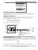
MODEL D AND D-V MICROPHONE
2 CONDUCTOR SHIELDED
22 GAUGE, with a 24 gauge drain wire
WEST PENN
452 OR EQUIVALENT
C
B
ABLACK
BLACK
BARE
BARE
REDRED
TO LOUROE
BASE STATION
OR
AUDIO
INTERFACE
ADAPTER
A
B
C
LOUROE ELECTRONICS 6 9 5 5 VA L J E A N AVENUE, VAN NUYS, CA 91406 TEL (818) 994-6498 FAX (818)994-6458
Website: www.louroe.com Email: sales@louroe.com
INSTALLATION AND OPERATING INSTRUCTIONS
2 Conductor shielded cable, 22
gauge with a 24 gauge drain wire
NOTE: Unshielded cable is not
satisfactory for audio systems
WIRING REQUIREMENTS
D/D-V MIC 1/08