
Manual

PAGE 2 OF 3
BAREBARE
A B CA B C
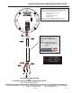
B AC K SI DE O F
V E R I FA C T A
M I C R O P H O N E
B A C K S I D E O F
V E R I FA C T A
M I C R O P H O N E
LL
NN
BLACKBLACK
REDRED
AA
BB
CC
BLACKBLACK
BAREBARE
REDRED
TO LOUROE BASE STATION
OR
TO OTHER LOUROE AUDIO RECORDING DEVICES
(IF-1, IF-2, IF-4, IF-8 ETC.)
A = +12Vdc (RED)
B = Audio (BLACK)
C = Ground (BARE)
LOUROE ELECTRONICS 6 9 5 5 VA L J E A N AVENUE, VAN NUYS, CA 91406 TEL (818) 994-6498 FAX (818)994-6458
Website: www.louroe.com Email
sales@louroe.com
INSTALLATION AND OPERATING INSTRUCTIONS
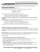
2 Conductor shielded cable, 22
gauge with a 24 gauge drain
wire.
NOTE: Unshielded cable is not
satisfactory for audio
systems.
WIRING REQUIREMENTS
MICROPHONE SENSITIVITY SWITCH
The microphone pre-amp (PC board) contains a sensitivity
switch with two positions marked N and L, and is located on the
back side of the Model A near the terminal block:
N represents normal sensitivity
(0 dB @ 1,000W)
L represents lower sensitivity
(-6 dB @ 1,000W)
Microphone is always shipped in the N position. For less
microphone sensitivity, move slide switch to L position.
A MIC 1/08