
Manual

MICROPHONE CONNECTION:
If using West Penn 452 or equivalent with same color code, connect:
1. Red wire (12 Vdc) connects to terminal A of microphone terminal block
2. Black wire (audio out) connects to terminal B of microphone terminal block
3. Bare wire (ground) connects to terminal C of microphone terminal block
INSTALLATION TIP: If area to be monitored for audio is noisy or has background disturbances, the microphone
should be positioned close to the subject (4’ - 8’) if possible. Also, the microphone sensitivity switch can be moved
from “N” position to “L” position to help reduce background noise. “N”is normal, “L” is low
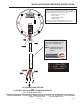
ELECTRICAL CONNECTION:
A represents +12 Vdc Power
B represents Audio Output
C represents Ground
A 3-pin terminal block is located on the back of the microphone housing, marked A, B, C.
CONNECTING VERIFACT A MICROPHONE TO A LOUROE BASE STATION OR AUDIO INTERFACE
ADAPTER
CONNECTING VERIFACT A MICROPHONE TO OTHER AUDIO DEVICES.
If a Louroe audio base station is not used and microphone is being connected directly to another source from other
manufacturers, 12 Vdc power must be applied to terminals A and C. (A is positive, C is negative). Terminals B and
C of microphone (C is common) go to the “Audio In” or “Line in” of the audio source. Wire from terminal B should
be shielded.
PAGE 3 OF 3
LOUROE ELECTRONICS 6 9 5 5 VA L J E A N AVENUE, VAN NUYS, CA 91406 TEL (818) 994-6498 FAX (818)994-6458
Website: www.louroe.com Email
sales@louroe.com
INSTALLATION AND OPERATING INSTRUCTIONS
INSTALLATION TIPS
1. Use overall shielded audio cable only. West Penn 452, Belden 8451 or equivalent.
UNSHIELDED CABLE IS NOT SATISFACTORY FOR SOUND SYSTEMS.
2. When used at a cash register checkout, microphone should be installed closer to the customer rather than the cash
register, as the drawer sound could dominate the recording. It should be installed closest to the
area to be monitored and documented.
3. Avoid installing microphone near air vents, air conditioners, fans and other equipment that generate
high sound and air pressure.
4. If microphone is installed in a police interview room, room should be conditioned with any type of carpeting, acoustical
ceiling tiles, acoustical foam, etc. to reduce echo. This will enhance the quality of live and recorded audio.
5. The APR-1 and microphone should have a barrier or solid wall between them in order to avoid audio
feedback, especially when they are in close proximity to each other. If no barrier, microphone should be at least 25’ from
APR-1 to avoid acoustical feedback.
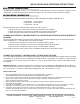
The Model A is cylindrical, 4” dia. x 1½” H, and has four mounting holes for surface mounting to a ceiling or other
flat surface. It should be positioned so that the microphone is 4’ to 8’ from the area of desired coverage.
All Louroe audio base stations (except the ALA-4/8 series) and Interface Adpaters have corresponding terminal
blocks marked A, B, C. Connect other end of cable as follows:
1. Red wire from microphone connects to pin A of Base Station (12Vdc)
If base station is ALA-4/8 series, please refer to installation instructions for the specific model.
2. Black wire from microphone connects to pin B of Base Station (Audio Output)
3. Bare wire from microphone connects to pin C of Base Station (Ground)
A MIC 1/08