
Instruction Manual


INSTALLATION AND OPERATING INSTRUCTIONS
Page 3 of 8
LOUROE ELECTRONICS® 6 9 5 5 VA L J E A N AVENUE, VAN NUYS, CA 91406 TEL (818) 994-6498 FAX 994-6458
website: www.louroe.com e-mail: sales@louroe.com
(818)
Ask4_350_inst 3/13
10
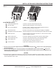
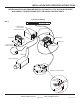
CONNECTING PoE SWITCH TO PoE IP CAMERA OR ENCODER (See Fig. 3)
1. Connect Ethernet cable from PSE (Power Source Equipment) to the Power+Data Input Jack of the IF-PX.
2. Connect Ethernet cable from camera to Power+Data Output Jack of the IF-PX. Camera should now have power
and data running through it. Power Indicator lights up.
3. Microphone Connection :
a) Connect a 2 cond. shielded cable to the terminal block of Louroe’s Verifact microphone. Connect the other end to
the pluggable header (Mic/Speaker Audio Terminal Block ) of the IF-PX. Connect terminal A of microphone to
terminal A of IF-PX; terminal B of microphone to terminal B of IF-PX; terminal C of microphone to terminal C of IF-
PX. Terminal SP of IF-PX is not used when connecting microphone only (one-way listen).
b) Using the patch cable (stereo plug to stereo plug), connect the Audio Output Jack of the IF-PX to the audio input
of the camera.
c) Adjust the Mic Out Adjust potentiometer (as needed) by rotating it clockwise to increase the microphone output to
the camera, or counterclockwise to decrease. This potentiometer is factory set for a gain of 0dB output.
(one-way listen)
See
interconnection diagram(Fig 3) on page 5.
4. Setup camera for video and audio monitoring. Use an amplified speaker on the computer to test the audio coming
from the microphone. See camera user manual for setting up the camera to the network.
CONNECTIONS AND OPERATIONS
The IF-PX can power most IP cameras and Encoders, check that the power requirements of the equipment does
not go beyond the IF-PX power output. See IF-PX power output below.
Power output of IF-PX:
12Vdc, 850mA with a Louroe microphone connected
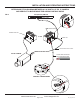
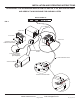
CONNECTING PoE SWITCH TO NON-PoE IP CAMERA OR ENCODER (See Fig 4)
1. Connect Ethernet cable from PSE (Power Source Equipment) to the Power+Data Input Jack of the IF-PX.
2. Connect Ethernet cable from Non-PoE Encoder or camera to Data Out Only Jack of the IF-PX.
8
1
5
9
2
8
7
3. Connect 2 wires to the DC Out Terminal Block . At least 20 AWG wires should be used between the IF-PX and the
encoder or camera. Positive 12Vdc connects to terminal marked “+12Vdc” of IF-PX. Negative 12Vdc or ground
connects to terminal marked “GND” of IF-PX. Connect the other end of the 2 wires to the power jack or terminal block
of the encoder or camera. If the encoder or camera has a 2.1mm power jack, an adapter (2-pin terminal block to
2.1mm male plug) can be used. Connect the wires to the 2-pin terminal block (observe polarity) of the adapter. Plug
the adapter to the 2.1mm power jack of the encoder or camera.
4. Repeat same procedure when connecting Louroe Verifact microphone to camera or encoder (steps 3 and 4 of -
Microphone Connections).
3