
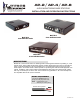
Manual
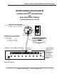

I MICROPHONE CONNECTIONS TO AP-2, AP-4 OR AP-8
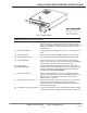
A 12Vdc power supply is included with the above units. First connect the small end with the 90° plug to the above units
DC Jack[11] and connect large end to a standard 120Vac outlet or power strip.
Maximum distance between AP-2, etc. and Louroe microphones is 1,000 ft. (305m)
II. CONNECTING AP-2/AP-4/AP-8 TO A RECORDING DEVICE (DVR, ETC.)
All Louroe Verifact Microphones contain a 3-pin terminal block marked A, B, C. All Louroe base stations contain similar
3-pin terminal blocks marked A, B, C. Refer to interconnection diagram p 5.
A = 12Vdc Power (red wire)
B = Audio Output (black wire)
C = Common Ground (bare wire)
1) Take one end of recommended cable to first microphone location and connect:
Red wire to terminal A (12Vdc)
Black wire to terminal B (Audio Output)
Bare wire to terminal C (Ground)
2) Run other end of to the AP-2, AP-4 or AP-8 Base Station location and connect to the 3-pin terminal
block of the audio zone in which the remote microphone is assigned (example zone 1). Again connect Red
wire to Pin A, Black wire to Pin B and Bare wire to Pin C.
3) Repeat the same procedure for the remaining microphones using the additional terminal blocks marked
zone 2, zone 3, etc.
cable
A) If connecting to a VCR or to a DVR with one audio input:
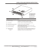
1) Connect an RCA cable to the Audio Out jack [13] of AP-2/AP-4 or AP-8 and connect other end to Audio In
(or line in) of VCR/DVR
2) To record, press the Zone Selector Switch [1] located on front panel of base station for the audio zone to
be recorded
3) For audio playback, connect another RCA cable from Audio Out (or line out) of VCR/DVR to Audio In [14]
of AP-2/AP-4/AP-8
4) Press in the VCR Button [7] of front panel
5) Press the play or playback button on VCR/DVR to start audio playback. Playback will be broadcast
through the base station’s built-in speaker. As an alternate playback may be channeled through a CCTV
monitor with amplifier or through DVR’s speaker system
2) If connecting to a DVR with multiple audio inputs or to a soundcard module:
AP-2, AP-4 and AP-8 have 2, 4 and 8 line level RCA Mic Output Jacks [15]
1) Connect RCA cables between the [15] and Audio Inputs of DVR
2) For audio playback from base station (AP-2, etc.), press in the VCR IN button [7] located on base station’s
front panel. Playback may also be channeled through other audio sources
3) To select a specific audio zone for playback, refer to DVR’s instruction manual
Mic Output Jacks
NOTE
Unshielded cable is not
recommended for this
installation
III APPLYING POWER TO THE AP-2, AP-4 OR AP-8
INSTALLATION AND OPERATING INSTRUCTIONS
2 Conductor shielded cable, 22
gauge with a 24 gauge drain wire
NOTE: Unshielded cable is not
satisfactory for audio systems
WIRING REQUIREMENTS
West Penn 452 or equivalent
PAGE 3 of 6
LOUROE ELECTRONICS 6955 VALJEAN AVENUE, VAN NUYS, CA 91406 TEL (818) 994-6498 FAX (818) 994-6458
Website: www.louroe.com Email: sales@louroe.com
AP SERIES 1/08