
Manual
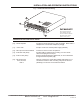
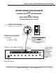

[6] - Filter Switch Normally used when playing back audio from a Time Lapse
(not used with DVR’s) recorder. When switch is pressed, the incoming audio is passed
through an audio filter network which enhances the quality of
recorded audio (not used with DVR’s).
[7] - DVR/VCR-IN Switch Press to connect DVR/VCR into the unit. Depressing switch
bypasses the DVR/VCR even if it is connected physically to the
back of the unit. This eliminates the need to disconnect the
DVR/VCR when not in use.
[8] - Power-Volume Control Knob Rotating knob clockwise turns on power to the unit, as indicated
by the Filter-OUT Indicator[2]. Rotating further clockwise
increases the volume of the monitored audio produced through
the Monitor Speaker[10].
[9] - Headphone Jack (3.5mm stereo) Used for private listening. Any monaural headset with 8 to 600W
impedance maybe used. Mutes the speaker output when in use.
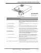
DESCRIPTION AND FUNCTION OF PARTS
[1] - Zone Selector Switches Selects zone for monitoring. Press switch of desired zone to
listen to live audio. Pressing more that one switch is possible
when it is necessary to monitor more than one zone at a time, but
audio may be difficult to understand if there is audio activity at
several zones.
[2] - Filter-OUT Indicator Lights (green) when audio filter is not in use. Indicates power is
“ON”.
[3] - Filter-IN Indicator Lights (red) when Filter Switch[6] is pushed in to “ON” position.
[4] - DVR/VCR-IN Indicator Lights (yellow) when DVR/VCR switch[7] is pushed in to “ON”.
[5] - Overload Indicator Lights (red) when a short or overcurrent in the power supply
occurs. If this occurs, turn OFF the Power-Volume Knob[8] and
check wiring connections (see troubleshooting, pg6).
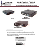
Fig. 1 Front of AP-8
S
N
E
G
N
O
H
R
E
D
V
L
L
A
E
I
Z I U
I
T
O E
A
U
C
E
I S
DU
A
MN
A
S
P
O
H
E
N
1
2
3
4
5
6
7
8
NZ
E
O
S
8
A
P-
O
F
F
X
A
M
W
P E
-
E
V
O
U
O
L
R M
R
N
V I
C
L
E
R
F
I T
E
S
S
P
R
B
A
P
L
K
A
Y
C
R
O
F
U
O T
N
I
O R
O
E
L
V
A
D
3
3
4
4
5
5
6
6
1
1
2
2
7
7
8
8
9
9
Fig. 1 Front view of AP-8
AP-2 and AP-4 have the
same features except
for the number of Zones
Fig. 1 Front view of AP-8
INSTALLATION AND OPERATING INSTRUCTIONS
PAGE 1 of 6
LOUROE ELECTRONICS 6955 VALJEAN AVENUE, VAN NUYS, CA 91406 TEL (818) 994-6498 FAX (818) 994-6458
Website: www.louroe.com Email: sales@louroe.com
AP SERIES 1/08