
Installation Guide


ADDITIONAL STEPS FOR ALUMINUM MODELS ONLY:
A. For aluminum models, complete table 4. Subtract ¾” from each measurement and record the results in row titled
“Rail cut length”.
B. Transfer cut length dimensions from table 4 to the bottom section of
the ladder right and left rails and draw a cutting line between the
two points. Trim bottom section to length using a metal cutting saw
(figure 7).
C. Rotate bottom section back in line with top sections and press
down on the middle section to ensure that the power arms
are fully extended.
D. Slide aluminum foot over ladder rail. Position foot so that the extended sections remain straight and the foot is in full
contact with the floor. Drill ¼” hole through the rail using the hole provided on the foot as a template. Anchor securely
with ¾” bolts and locknuts provided.
EVEREST ALUMINUM 12’ FOLDING ATTIC LADDER OPENING AND CLOSING INSTRUCTIONS
Closely follow instructions attached to pole hook
when opening and closing Everest Folding Attic ladder.
Required to operate: Two People | Attic ladder Pole hook | Stepladder or Step Stool
Opening Instructions:
1. Standing on the floor, reach up with the pole hook and firmly hook the eye–bolt on the attic door and pull to open door.
2. Position a stepladder to the side of the attic ladder’s climbing section drop–down area.
DANGER: never place stepladder or person in the path of the attic ladder’s climbing section drop–down area.
3. Position the two people (one on the stepladder and one on the floor) on either side of the attic ladder drop–down area.
4. The person on the stepladder should slowly and carefully begin unfolding the two hinged sections of the attic ladder to
the person on the floor.
5. Continue to unfold the attic ladder until both sections are fully extended. Press downward on the climbing section to
ensure power arm assembly is fully open and in the locked position.
Closing Instructions:
1. Position one person on the stepladder and the other on the floor on either side of
the attic ladder.
2. The person on the floor should begin to fold up the bottom and middle sections,
handing off to the person on the stepladder to complete the folding process.
3. Use the pole hook to tap the power arm toward the open end of the attic ladder
(away from the door hinge) to release power arm (See figure 12).
4. Hook the eye–bolt on the door with the pole hook and push firmly upward until the
springs engage. Slowly control the door with the pole hook until completely closed.
5. Remove pole hook and store in a safe place.
CHECK THE LENGTH AFTER MAKING YOUR CUTS
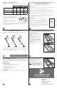
Again, be sure the attic ladder power arms are fully extended. Trimmed correctly, your attic ladder should look like figure 9.
Verify that there are no gaps in the section and both feet are flat on the floor.
If the attic ladder looks like figure 10, then both of the legs are too long and need to be trimmed further.
If the attic ladder looks like figure 8, then both of the legs are too short, and the attic ladder is not safe to use. A new
lower section would need to be purchased from the manufacturer.
ADJUSTING THE SPRING TENSION (IF NEEDED) [CS305P & CL305P models only]
Your attic ladder is equipped with a unique and easy way to adjust the tension on each of the two springs. With the attic
ladder in the closed position, use an adjustable or ⁄” wrench and tighten (turn clockwise) the red kep nut on the J-bolts
that attach the springs to the door panel. Alternate the tightening of each spring to raise the door panel evenly so it ends
up flush with the ceiling.
INSTALLING HARDWARE
A. Ladders with pull cord and pendant.
• Thread pull cord through pre–drilled hole in door and tie a knot in end of cord.
• Be sure the knot is large enough to not slip through the hole.
B. Ladders with eye–bolt and pole hook.
• Slide eye–bolt through the hole in the attic ladder door.
• Install washer onto eye–bolt on the opposite side of the door.
• Securely fasten nut onto the eye–bolt.
TRIM INSTALLATION
To install trim molding leave ⁄” clearance between the door panel at the hinge end and ⁄” clearance on the other 3 sides.
For customer service, call Louisville Ladder at
1–800–666–2811 or e–mail info@LouisvilleLadder.com
FIGURE 13
Header
Header
54”
Diagonal
Measurements
Nails
(figure 15)
• Locate double headers at each end of opening and secure
with (3) 16d nails into each end of the headers.
• Install stringer and check for squareness by making sure that
diagonals are within ⁄”.
• Secure using (3) 4” nails into each end of the stringer.
CAUTION: Consult an engineer or obtain architectural
approval for installations that require the
removal of roof trusses or rough openings
perpendicular to the ceiling joists.
Customer service: 1–800–666–2811 or e–mail info@LouisvilleLadder.com
FIGURE 14
Temporary Support
Boards
Louisville Ladder Inc.
7765 National Turnpike, Unit 190
Louisville, KY 40214
1–(800)–666–2811 (U.S. & CANADA)
1–(502)–636–2811 | FAX: 1–(800)–274–4566
www.LouisvilleLadder.com
Spring–based Attic Ladder Installation Instructions 2014 v1 [F9018]
April 2014 | © 2014 Louisville Ladder, Inc. All rights reserved.
LEFT RAIL RIGHT RAIL
A B A B
Measurement to floor
Subtract for shoe
(-¾”) (-¾”) (-¾”) (-¾”)
Rail cut length
TABLE 4 (Aluminum models only)
FIGURE 8 FIGURE 9 FIGURE 10
Gap No gap
Feet flush
with floor
Feet ARE NOT
flush with floor
GapNo gap
FIGURE 12
FIGURE 7 (repeated from previous page)
CUTTING
LINE
APPENDIX – Framing A Rough Opening Parallel To Ceiling Joist
Make a rough opening to the size as required in table 2 (page 3) ensuring that the dimensions of the diagonals of the
frame are the same as illustrated in figure 13.
A. For Rough opening without joist removal
(figure 13)
• Locate headers in front and rear of the opening as shown in
figure 13.
• Check for squareness by making sure that diagonal
measurements are within ⁄”.
• Secure using (3) 16d nails into each end of the Header.
B. Rough opening with joist removal (figure 14)
• Install temporary support boards spanning both sides of
joists to be removed.
• Remove joist at length to allow for double headers to be
installed on both ends of opening.
Continued on next page...
FIGURE 15
Headers
Headers
Nails
Diagonal
Measurements
Stringer
8
9
10
11
12
7