
Owner's Manual


4
Connecting the Camera
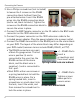
3. Use a Philips screwdriver (not included)
to loosen the 2 screws on the RS485
connection block furthest from the
pre-attached wires.
Loosen screws
Insert wires
Insert the RS485
wires into the RS485 connection block
(red t
o red, black to black). Tighten the
screws on the RS485 connection block to
secure the wires in place.
4. Connect the BNC female connector on the 3ft c
abl
e to the BNC male
connector on the 100ft extension cable.
5. Connect the power connector on the 100ft e
x
tension cable to the
included power adapter. Plug the power adapter into a power outlet.
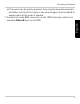
6. Connect the RS485 connectors to the RS485 ports on the alarm bl
ock
on y
our DVR. The layout of the alarm block may differ depending on
your DVR model (common terms include RS485, RS422, or PTZ).
• The RS485 connectors are a pair
of
bare 24-gauge wires. The red
wire is positive (+) and is
connected to the + port on the
RS485 section of the alarm
block, and the black wire is
negative (-) and is connected to
the - port.
Spring loaded lock alarm block
Screw lock alarm block
Insert a
screwdriver and
then insert wires
+ / - RS485 Ports
+ / - RS485 Ports
Tighten screws
above ports to
secure wires
• Most DVR’s either use screws or
a spring loaded lock to hold the
RS485 wires in place. For a
spring loaded lock, insert a
screwdriver or small object into
the lock, insert the wires, and
then remove the screwdriver to
lock the wires in place.