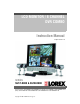
LCD MONITOR / 8 CHANNEL DVR COMBO Instruction Manual English Version 1.0 SERIES: SG17LD800 & SG19LD800 www.lorexcctv.com Series Includes: SG17LD800 & SG19LD800 Series (NTSC); SG17LD800P & SG19LD800P Series (PAL); SG17LD804-161 & SG19LD804-161; SG17LD804P-161 & SG19LD804P-161 Copyright © 2007 LOREX Technology Inc.
Thank you for purchasing the LCD / 8 Channel DVR Combo. Lorex is committed to providing our customers with a high quality, reliable security product. This system offers a whole new level of security surveillance to the consumer market.
Important Safeguards Important Safeguards In addition to the careful attention devoted to quality standards in the manufacture process of your video product, safety is a major factor in the design of every instrument. However, safety is your responsibility too. This sheet lists important information that will help to assure your enjoyment and proper use of the video product and accessory equipment. Please read them carefully before operating and using your video product. Installation 1.
Important Safeguards Service Use 13. Servicing - Do not attempt to service this video equipment yourself as opening or removing covers may expose you to dangerous voltage or other hazards. Refer all servicing to qualified service personnel. 19. Cleaning - Unplug the video product from the wall outlet before cleaning. Do not use liquid cleaners or aerosol cleaners. Use a damp cloth for cleaning. 14.
General Precautions NOTE This equipment has been certified and found to comply with the limits regulated by FCC, EMC, and LVD. Therefore, it is designated to provide reasonable protection against interference and will not cause interference with other appliance usage.
LCD/DVR COMBO FEATURES LCD/DVR COMBO FEATURES • Professional A-Grade LCD with ultra fast 8ms refresh rate and wide viewing angle (+/- 75 degrees vertical and horizontal) • Pentaplex operation - simultaneously functionality: z Live Viewing z Recording z Playback z Backup z Network Controls • MPEG4 Compression: Small File sizes without comprised video quality • Installed Seagate SV35 Series HDD: Hard Drives specifically designed for optimal performance in the commercial video security market.
Table of Contents Table of Contents Getting Started .......................................................................................... 9 Front Panel ........................................................................................ 10-13 Rear Panel ......................................................................................... 14-15 Remote Control ....................................................................................... 16 MC7520 Cameras ...............................
Table of Contents Disk Management ................................................................................... 49 Recording Menu Controls .................................................................. 50-51 Recording Menu Options ........................................................................................................... 50 Recording Operations ................................................................................................................
Getting Started Getting Started The system comes with the following components: 4 x CAMERAS WITH STANDS LCD & DVR COMBO UNIT WITH INSTALLED 160 GB HDD POWER ADAPTER REMOTE CONTROL 4 x 100 FT. (30M) EXTENSION CABLES ETHERNET CABLE HARDWARE & SOFTWARE MANUALS & SOFTWARE CD CHECK YOUR PACKAGE TO CONFIRM THAT YOU HAVE RECEIVED THE COMPLETE SYSTEM, INCLUDING ALL COMPONENTS SHOWN ABOVE.
Front Panel Front Panel 1 7 8 9 10 2 3 4 5 11 12 13 14 6 15 16 1. REW BUTTON - Reverses the playback of the currently displayed Video 2. FF BUTTON - Fast forwards the playback of the currently displayed Video 3. DISPLAY - Changes the onscreen Camera display: • Single - Displays a single camera onscreen • Quad - Displays 4 cameras onscreen • 6 Camera Display - Displays 6 cameras onscreen.
Front Panel 4 5 6 7 4. PTZ BUTTON - Accesses the PTZ (Pan/Tilt/Zoom) Menu. Refer to page 35 for Pan/Tilt/Zoom options NOTE: PTZ option will only work with PTZ type cameras (not provided with this unit). Visit the Lorex website at http://www.lorexcctv.com for a full range of Pan/Tilt/Zoom Cameras. 5. SEARCH BUTTON - Opens the Search Menu to view previously recorded data. Refer to page 25 for detailed search options. 6.
Front Panel 8 9 10 11 8. CHANNEL SELECT BUTTONS - Displays individual camera views. Also used to input the system Password when accessing the Setup Menu. 9. RETURN BUTTON • Returns to a previous screen in Menu Mode. • Exits from Menu Setup (when in the Main Menu screen). Exits from Search and PTZ Modes. 10. PLAYBACK / NAVIGATION CONTROLS • Controls the playback of video (Play / Pause / Fast Forward / Rewind), and controls the viewing area in PTZ Viewing Mode.
Front Panel 12 13 14 15 16 12. SEQ BUTTON - Used to Sequence between all camera locations in Full Screen mode (in sequential order). To exit Sequence Mode, Press the SEQ button again 13. ZOOM BUTTON - This monitor is equipped with digital ZOOM. To utilize this feature proceed as follows: • Set the monitor to full screen mode for the desired channel • Press the ZOOM button. ZOOM mode is now active • Use the Navigation Buttons [ ÇÈÅÆ ] keys to move the area being captured in ZOOM MODE.
Rear Panel Rear Panel 1 9 8 2 3 4 5 6 7 1. 6 PIN DIN CAMERA INPUTS - Channel 1-8 Camera inputs (for cameras with 6 Pin DIN connections). DIN type cameras are provided with the System. Cameras with 6 Pin DIN connections draw power from the System - additional power adapters are not needed. 6 PIN DIN 2. RCA AUDIO INPUTS - Channel 1-4 Audio inputs (for BNC type cameras with standard RCA Audio output) 3. BNC VIDEO INPUTS - Channel 1-8 camera inputs (used to connect Cameras with BNC connection type).
Rear Panel 9 8 4 5 6 7 4. SPOT OUT - Video Output port to connect the unit to a secondary DVR or TV 5. AUDIO OUT - Audio Output port to connect the unit to a secondary DVR or TV 6. ALARM FUNCTION TERMINALS (INPUT/OUTPUT) - These terminals are used to connect external alarm devices such as a motion sensor, door/alarm sensor, or time lapse VCR for Alarm Recording. Refer to page 73 for Alarm Block Configuration. 7.
Remote Control Remote Control Listed below is a quick reference for the Remote Control. POWER BUTTON Turns the system power ON/OFF SETUP BUTTON Opens the Main Menu (system setup) REMOTE ID* Configure when using multiple systems.* CHANNEL BUTTONS Press to select a specific camera by number RETURN BUTTON Returns to the previous selection in Menu Mode. Exits the Menu Setup when in the Main Menu. AUDIO SELECT Press to select an audio channel. Press the Audio select button, then a channel 1~4.
MC7520 Cameras MC7520 Cameras The System includes 4 CCD Color IR Day/Night Indoor/Outdoor Cameras* INFRA-RED LEDs Provides illumination for low light conditions CAMERA LENS MICROPHONE Picks up sound near the camera and transmits to the System (located on the rear of the camera). STAND Stand connects to the Camera for mounting to walls, ceilings and other surfaces INPUT CABLE Connects Video / Audio / Power from the System * Picture changes from Color to B&W under low light conditions.
Camera Installation Camera Installation Before you install the camera, carefully plan where and how you will position the camera, and where you will route the cable that connects the camera to the System. Installation Warnings: • Select a location for the camera that provides a clear view of the area you want to monitor, which is free from dust, and is not in line-of-sight to a strong light source or direct sunlight.
Camera Installation Connecting Cameras 1. Connect the female end of the supplied 100’ extension’ cable to the camera. NOTE: Confirm that the arrows on the DIN Camera Cable and the DIN Extension cable are pointed together when connecting the cable. If the pins in the DIN Cable are bent, the Camera will NOT function. 2. Connect the male end of the supplied 100’ extension cable to an open DIN camera input on the back of the System. Continue connecting additional DIN cameras.
Display Modes Display Modes Initial Loading Sequence • Press the POWER button located on the front panel of the Observation System to start the unit. • The System will perform a Hard Drive check NOTE: This unit includes a 160GB Hard Drive. • The unit will initially load to a split screen view, displaying all 8 cameras (if available). NOTE: If a new HARD DRIVE is detected, the system will prompt you to FORMAT the drive.
Display Modes Network Connectivity Indicator The Network Indicators appear when a remote connection is made to the unit via the Remote Agent software, or through the Internet Explorer Web Client: • Green: Indicates that the network connection is stable. • Blue: Indicates that the network connection is experiencing difficulties. • Red: Indicates that the network is unstable.
Display Modes Zoom Mode • Displays the Camera in ZOOM Mode. • Use the Arrow keys to adjust the Zoom location. • Press the Return key to exit ZOOM Mode. Covert Camera Mode • Displays the Camera in Covert Mode. • The Camera is not displayed - an empty blue screen is displayed instead of the Video. • Covert cameras are configured from the Menu. See Page 34. Camera Volume Display Mode • Displays the Camera currently sending Audio. • The Camera Volume can be controlled using the up and down arrows.
PTZ (Pan/Tilt/Zoom) & Focus Controls PTZ (Pan/Tilt/Zoom) & Focus Controls The PTZ / Focus Menus will only work with PTZ type cameras (not included): PTZ Control Screen Focus Control Screen Press the PTZ Button on the front panel of the system, or on the Remote Control to access the PTZ Control Screen: Press the PTZ Button a second time to access the Focus Control Screen: • The onscreen icons represent buttons on the front panel and remote control (up/down/left/right).
System Power Off System Power Off Monitor Display Shutoff • Press the Power Button on the front panel or remote control for one second to turn off the monitor only. • The System will continue to record while the monitor is off. • The LED indicators on the front of the System will remain ON. • The monitor shutoff can be automatically set using the Screen Saver settings in the System Menu (refer to page 33).
Search Mode Search Mode Search mode allows you to locate previously recorded video by Date and Time, or by Event Type. • Press the Search Button on the front panel or Remote Control • Enter the User Name and Password (if required). • Use the Left / Right arrows on the Front Panel or Remote Control to switch between the Search By Time and Search By Event screens. Search By Time Searches the system based on date and time.
Search Mode Search By Event Searches the system based on Event Type (Alarm, Motion, Continuous or System). • Press the right arrow button on the front panel or remote control to access the Search By Event screen. • Select From and To dates, Events (Alarm, Continuous, Motion and Other) and Cameras • Navigate within the options using the Arrow Keys on the front panel or remote control. Press the Enter button to select or deselect options (Note: Multiple event types can be selected).
Menu Navigation Controls & Tips Menu Navigation Controls & Tips Menu Navigation Controls Navigation Controls - Move Up/Down/Left/Right. Enter Button - Press this button to select and change the values in a menu option. Return Button - Complete modifications of a menu option; exit a menu Virtual Keyboard Control The Virtual Keyboard control becomes available when keyboard input is needed for entering information such as Names, Network Information, etc. • Includes a~z, A~Z, 0~9 and Symbols.
System Setup Controls System Setup Controls • Enter the MENU screen by pressing the MENU button. Enter the password (if required), and select the SYSTEM SETUP option. • Scroll through the 6 options by pressing the UP, DOWN, LEFT and RIGHT buttons on the Front Panel or Remote Control. • To enter a sub-menu, navigate to the option and press the ENTER button. To exit a SUBMENU, press the RETURN button. • To exit the MAIN MENU, press the RETURN button. DISPLAY - Setup of display options.
Display Menu Display Menu The Display Menu controls: OSD - Onscreen display settings control the camera titles, event indicators, and general screen settings. MONITOR - Display settings for Alarm and Events SEQUENCE - Controls for the display of video images in Sequence Mode SPOT-OUT - Sends camera video to a secondary monitor (by individual camera based on Menu Settings) through the SPOT-OUT Port.
Display Menu OSD (Onscreen Display) • Motion Sensor Display - Turns the display of the Motion Sensor to: - Active: Display motion sensor of motion detection area. z - Inactive: Display motion sensor except motion detection area. z - Off: No display of motion sensor. z • Motion Sensor Color - Sets the motion sensor color. When Motion is detected on a channel, the moving parts of the image will be highlighted with colored squares (i.e. Blue Squares). • Motion Transparency - Setup motion transparency.
Display Menu SEQUENCE Sets the Sequence Mode for the display of available channels. • Activation - Turns the Sequence ON/ OFF. NOTE: Up to 16 different Sequence Mode settings can be configured, however only ONE can be active at a time. • List - Displays the Sequence Title • Created By - Displays the user that created the Sequence.
Display Menu SEQUENCE SETUP MODE 1. Press the ENTER button. Setup Mode is active. 3. Press the Number Keys to Select channels to be displayed in Sequence (all squares must have an assigned number). 5. Press the RETURN button when complete. Select SAVE & EXIT. 32 2. Select the Display Mode (5 different Display Options - Single, Quad, 6, 8A & 8B). 4. Choose the next Display Mode (up to 16 additions). 6. Press the SEQ button on the Front Panel to switch to Sequence display.
Display Menu SPOT-OUT Sends the Specified camera video to a secondary Monitor (via the Spot Out Port on the back of the unit). • Check or Uncheck the selected Cameras to have the video sent to a Secondary Monitor in Sequence. NOTE: Any cameras NOT checked will not be sent as video to the Spot Out Monitor. SCREENSAVER • Auto Brightness - Sets the length of time before the Screen brightness is turned down (up to # minutes).
Camera Menu Camera Menu The Camera Settings and Controls: CAMERA TITLE - Settings for the onscreen display of individual Camera Titles. COLOR SETUP - Color settings for individual cameras. PTZ SETUP - Configuration for PTZ type cameras (not included with the system). MOTION SENSOR - Configuration for Video Motion Detection. CAMERA TITLE • CAM # - Indicates the Camera Number (corresponds to the DIN/BNC connection port on the back of the system). • Covert - Turns the onscreen display of the Camera ON/OFF.
Camera Menu COLOR SETUP Displays the settings for Brightness, Contrast, Tint and Color for individual cameras. • Press the ENTER Button and select a camera. • Set the Brightness, Contrast, Tint and Color for each camera. These settings can be set to a range of 1(low)~100(high) • Press the RETURN button to return to the Camera Color Setup screen. PTZ SETUP PTZ Setup is for PTZ Type Cameras ONLY, which are not included with this system. For more information on PTZ Cameras, visit us on the web at http://www.
Camera Menu PTZ PROPERTIES • Channel No. - Camera Number. • PTZ Driver - The compatible driver selected for the PTZ Camera. • Auto Focus - Sets the Automatic camera focus to ON/OFF. • Auto Iris - Sets the Automatic Shutter to ON/OFF. • Speed Controls - Sets the Pitch, Zoom, Focus and Iris speeds between 1~5. MOTION SENSOR • Sensitivity - Controls the Motion Sensitivity for the individual camera between 1 (low) ~ 10 (high).
Sound Menu Sound Menu The System Sound settings: AUDIO - Settings for the system Audio for Live and Remote monitoring. BUZZER - Settings for System Buzzer (audible alerts). SOUND • Live Audio - Turns Live System Audio (from the Audio on the terminal) to ON/ OFF. • Audio Monitoring Channel - Select the channel for Listen-in Audio (Channels 1~4 ONLY). NOTE: Listen In Audio only works with Channels 1~4. Other channels will send audio which will be Recorded.
System Menu System Menu The System Setting controls contain: DATE/TIME - Date and Time controls for the system. NETWORK - Network and remote access controls. MAIL - Mail setup USER MANAGEMENT - Controls for system users. SYSTEM MANAGEMENT - System specific settings and controls CONTROL DEVICE -? DATE/TIME • Date/Time - Sets the current system Date and Time.* • Date Format - Sets the Date Display format (MM-DD-YYYY, YYYY-MM-DD, etc.).
System Menu NETWORK • DHCP (Dynamic Host Configuration Protocol) - Allows the System to receive Network Information from the DHCP Server (i.e. The local Router). If DHCP is set to ON, the IP Address, Gateway and Subnet Mask will be assigned by the DHCP Server (i.e. The local area network Router. The Router is not included with this system). z If DHCP is set to OFF, the Network Information will need to be assigned manually.
System Menu NETWORK • 1st / 2nd DNS Server - Automatically detected if DHCP is set to ON. Displays the IP address of the local DNS Server (i.e. local Router). • DDNS Server - Set to the free DDNS Server provided by Lorex (ddns.strategicvista.net). • Net Client Port - Default port of 6100. Used for remote connection. • Web Server Port - Default port of 80. Used for remote connection. • Max TX Speed - Sets the default Maximum Data Transfer speed for the remote connection (default of 8192 KB/ sec.).
System Menu USER MANAGEMENT • User setup consists of 3 groups: Administrator, Manager or User. • Up to 7 new users can be added to the system. • ADD - Opens the ADD New User screen to configure the new user settings NOTE: A maximum of 4 users can be remotely connected to the System simultaneously. ADD User Screen • User ID - Enter an ID (Name) for the new user • Password - Enter a password for the New User • Group - Enter the permissions level: Admin - Highest Level Access.
System Menu SYSTEM MANAGEMENT • System Information - Navigate to the PRESS button, and choose ENTER to display the System Information. • System Name - Input a name for the system using the Virtual Keyboard. • FW Update - Navigate to the PRESS button, and choose ENTER to update the System Firmware. • Factory Default - Navigate to the PRESS button, and choose ENTER to reset the System to Factory Defaults. • System Data - Saves or Loads the System Data (system settings).
System Menu SYSTEM MANAGEMENT Firmware Update New firmware is periodically available for download from the www.lorexcctv.com website. The firmware on the unit can be updated via the USB Port: • Download the new firmware from the website. Copy the files from the PC to the USB Memory Stick. • Insert the Memory Stick into the System. Select the ‘Firmware Update’ option by selecting the PRESS button. • The USB device will be recognized by the system - Press the START button to display the available firmware.
System Menu SYSTEM MANAGEMENT Factory Defaults The System can be returned to the Factory default settings: • Select the ‘Factory Defaults’ option by selecting the PRESS button. • Choose OK to reset the unit, or CANCEL to exit without resetting. NOTE: If the System is reset to Factory Defaults, all settings will be lost (except the Date and Time).
Event / Sensor Event / Sensor The Event Sensor Setting controls contain: HDD EVENT - Checks the Hard Drive for errors. ALARM IN - Configuration settings for an external Alarm sensor (i.e. Door / Window Sensors). ALARM OUT - Sends a signal to an external device when an alarm is detected. BUZZER OUT - Turns the audible Buzzer ON/OFF for selected event types. E-MAIL NOTIFICATION - Sends and E-Mail notification when a selected event occurs (based on User Configuration settings).
Event / Sensor ALARM INPUT Configurations for any external alarm device (i.e. a Door or Window Sensor). Refer to page 73 for hardware configuration details. • Operation - Sets the Alarm Sensor Connection Status (Enable / Disable) for an external alarm (i.e. Door or Window Sensors). Refer to page 73 for setup diagram. • Type: Sets the Alarm Sensor type to N/ O (Normally Open) or N/C (Normally Closed).
Event / Sensor ALARM OUT • Duration - Sets the Reacted Relay Time. (5sec~5min or Until key-in) • HDD Event - Turns the Alarm ON/OFF when the Hard Drive experiencing problems. • Alarm - Sends the Alarm Out when an Alarm Event is detected (set to ON/ OFF). • Video Loss - Sends the Alarm Out when a Video Loss Event is detected (set to ON/OFF). • Motion - Sends the Alarm Out when a Motion Event is detected (set to ON/ OFF). BUZZER OUT Generates a Buzzer when an alarm is detected.
Event / Sensor EMAIL NOTIFICATION • Notification - Sets the E-Mail notification ON/OFF. • HDD Event - A notification is sent if a Hard Drive event is detected (set to ON/ OFF). • Notifications can be enabled for each channel for: z z z Alarm Video Loss Motion can be selected NOTE: Emails will be sent at 15 minute intervals for the duration of the Event.
Disk Management Disk Management • Record Time Limit - Setup for the Recording Time Limit (between 12 hours ~1 month) NOTE: The Record Time Limit refers to the length of time data will be kept on the drive. For example: The Record Time Limit is set to 7 days. The System records data from the 1st of the month through the 7th of the month. On the 8th of the month, it will begin overwriting data (hour by hour) that occurred on the 1st of the month.
Recording Menu Controls Recording Menu Controls • Enter the RECORDING MENU screen by pressing the MENU button. Enter the password, and select the RECORDING MENU option. • Scroll through the 3 options by pressing the UP, DOWN, LEFT and RIGHT buttons on the Front Panel or Remote Control. • To enter a sub-menu, navigate to the option and press the ENTER button. To exit a SUBMENU, press the RETURN button. • To exit the MAIN MENU, press the RETURN button.
Recording Menu Controls Recording Operations • RECORDING MODE - Changes the Recording mode from Simple to Advanced (see below). • SCHEDULE MODE- Sets the Scheduled Recording Mode to Daily or Weekly. • PRE EVENT RECORDING - When an alarm is detected, the Pre Alarm will begin recording before the Alarm was detected (retrieved from video cache). The Pre Alarm Recording Time can be set to between 1~5 seconds.
Simple Recording Mode Simple Recording Mode • Recording Quality - Sets the video recording quality to Low, Standard, High or Highest. • Recording Size - Sets the video capture size for all camera to 352x240, 704x240 or 704x480. • FPS - Sets the Frames Per Second for recording across all channels. Each channel can be set to 1, 2, 3, 7, 15 or 30 Frames per second (real time video capture) from a shared pool of 120 FPS.
Advanced Recording Mode Advanced Recording Mode Continuous / Motion Setup • PARAMETER MODE - Contains the general recording parameters for each camera • SCHEDULE MODE - Contains the schedule recording settings for each camera. NOTE: Audio Recording ONLY works on Channels 1~4. Continuous / Motion Parameter Mode Parameters for each camera are set by hour using the Time Interval bar. Time Interval Bar Press the ENTER key to select the Interval Bar, and navigate using the arrow keys.
Advanced Recording Mode Continuous / Motion Schedule Mode Sets the Timer or Motion recording for each channel (by hour). Press the ENTER key to enter the Camera Selection window, and navigate using the arrow keys. Select an Hour (highlighted in Green), and press ENTER again to open the settings window. • None - No recording schedule is set. • Continuous - The system constantly records the camera based on the hourly setting.
Advanced Recording Mode Alarm Setup Mode • PARAMETER MODE - Contains the general recording parameters for each camera • SCHEDULE MODE - Contains the schedule recording settings for each camera. NOTE: Audio Recording ONLY works on Channels 1~4. Alarm Parameter Mode Parameters for each camera are set by hour using the Time Interval bar. Time Interval Bar Press the ENTER key to select the Interval Bar, and navigate using the arrow keys.
Advanced Recording Mode Alarm Schedule Mode • Sets the Alarm recording for each channel (by hour). • Press the ENTER key to enter the Camera Selection window, and navigate using the arrow keys. • Select an Hour (highlighted in Green), and press ENTER to set to Alarm (highlighted) or None (no highlight): NONE ALARM • Select the RETURN button to apply the changes.
Archiving Archiving The Archive feature copies data from the Hard Drive to a USB backup media such as a Memory Stick or USB Hard Drive • Enter the ARCHIVING screen by pressing the MENU button. Enter the password, and select the RECORDING MENU option. • Scroll through the options by pressing the UP, DOWN, LEFT and RIGHT buttons on the Front Panel or Remote Control. • To enter a sub-menu, navigate to the option and press the ENTER button. To exit a SUBMENU, press the RETURN button.
Archiving Archiving Options Once the Start Time, End Time and Channel Selections have been completed, select the START Button A Drive Usage report will be displayed: • Amount of space (in MB) needed • Start and End Times for Each Channel, with size of recordings (in MB) • Size of the Log File Select OK to begin the backup The Writing status window displays the completion state of the Backup (in%) The Extracting status window displays the completion state of the Extraction of previously archived data (in%
Network Connectivity Overview Network Connectivity Overview The Observation System can be remotely controlled using your existing network and the provided software. 1. Connect the Observation System to the Router using the supplied Ethernet Cable. Power the Observation System on. NOTE: The Observation System must be connected to the router prior to powering on the system. This allows the system to communicate on your network 2.
Network Connectivity Overview IP & MAC Address The IP & MAC Addresses are necessary for DDNS Setup (for remote access to the Observation System). To Locate the System information, Press the ENTER button on the Front Panel or Remote Control while viewing the Cameras. The System Info window will be displayed. - OR 1. Press the Menu Button on the Front Panel or Remote Control to access the Setup Menu. Select the System Setup option and press the Enter button. 2. Navigate to the System Menu option.
Network Connectivity Overview Setting Up Your DDNS Account Lorex offers a free DDNS service for use with your System. A DDNS account allows you to set up a web site address that points back to your Local Network. The following outlines how to set up your free DNS account. 1. Navigate to http://DDNS.strategicvista.net 2. Select the Create Account option from the list on the left side of the screen. 3. Complete the Account Information fields with your personal information 4.
Network Connectivity Overview 5. Click the Create New Account link at the bottom of the form to submit your request. 6. Your Account information will be sent to you at the E-mail Address you used in Step 3. Service provider: User Name: Domain Name: Password: dns1.strategicvista.net tomsmith1 tomsmith (your password) You will need this information for remote access to your System.
Network Connectivity Overview Router Port Forwarding How do I enable Port Forwarding on my Router? You will need to enable port forwarding on your Router to allow for external communications with your Observation System for ports: • TCP/IP PORT 6100 • WEB PORT 80 Computers, Observation Systems, and other devices inside your network can only communicate directly with each other within the internal network. Computers and systems outside your network cannot directly communicate with these devices.
Network Connectivity Overview DDNS SETUP Once the DDNS settings have been configured online, the information must be entered on the Observation System to allow for remote connection via the Lorex Client Software (or through Internet Explorer): 1. Access the Main Menu Setup screens, and navigate to the SYSTEM option. Press the ENTER button to access the setup. 2. Navigate to the NETWORK option. Press the Enter button to access the Network settings.
Troubleshooting Troubleshooting When a malfunction occurs, it may not be serious and can be corrected easily. The following describes the most common problems and solutions. Please refer to the following before calling Lorex Technical Support: Problem: Observation System Unit is not receiving power, or is not powering up Check: • Confirm that all cables are connected correctly. • Confirm that the power adapter is securely connected to the back of the unit.
Troubleshooting Problem: The image on the Observation System is too dark or too bright Check: • Adjust the CONTRAST and BRIGHTNESS of the unit (Refer to the Menu section) Problem: The image on the Observation System does appears, but does not have sound Check: • Check the VOLUME • Check the CAMERA connection to the Observation System • Confirm that the Camera has sound capabilities (Refer to the manual for the camera model for further information on the Camera functionality) Problem: The picture on the O
Observation System Specifications - Appendix #1 Observation System Specifications - Appendix #1 Display Specifications Video Standard NTSC / PAL LCD 17” or 19” Resolution 704x480, 704x240, 352x240 (NTSC) 704x576, 704x288, 352x288 (PAL) Monitor Display Real Time 30 FPS NTSC (per camera) Real Time 25 FPS PAL (per camera) Compression Standard MPEG4 Image Size 3-5 KB (352x240 NTSC, 352x288 PAL) 5-10 KB (704x240 NTSC, 704x288 PAL) 6-16 KB (704x480 NTSC, 704x576 PAL) Video Inputs 8 x 1Vp-p, CBVS, 75
Observation System Specifications - Appendix #1 Observation System Specifications - Appendix #1 Alarm Specifications Alarm Inputs 8 x TTL, programmable as NC or NO Alarm Outputs 1 x relay with NO/NC Contact 30V DC/1A, 125 VAC/0.
Observation System Specifications - Appendix #1 Observation System Specifications - Appendix #1 Network Specifications Network Interface 8 Levels (56KB ~ 8MB)/sec. Remote Access View, Search, Record and Control via Software or Internet Explorer Network Protocol TCP/IP, DDNS and Web Network Interface 10/100 Base-TX; RJ-45 System Specifications Supply Voltage 100 VAC - 240 VAC, 5A, 60/50Hz Power Consumption Aprox.
MC7520 Camera Specifications - Appendix #2 MC7520 Camera Specifications - Appendix #2 Image Device 1/4" Interline transfer type color CCD Effective Pixels NTSC: 512 H x 492 V (252k PIXELS) PAL: 512 H x 582 V (298k PIXELS) Scanning System NTSC: 525 Lines 2:1 Interlace PAL: 625 Lines 2:1 Interlace Resolution Horizontal 350 TV lines Shutter Speed NTSC: 1/60 ~ 1/10,000 sec. PAL: 1/50 ~ 1/10,000 sec. S/N Ratio More than 48dB (AGC off) Sync. System Internal Min. Illumination 1.
Lorex Client Software Requirements - Appendix #3 Lorex Client Software Requirements - Appendix #3 The Lorex Client software (included with the Observation System) has the following installation requirements. Minimum System Requirements: Operating System Windows 2000 Windows XP Home Edition Windows XP Professional Processor .Pentium 4 - 1.5 GHz Processor (or equivalent) Memory 256 MB RAM Hard Drive 50 MB - Installation space required * Additional Hard Drive space required for recording.
Connecting a Slave (Spot-Out) Monitor - Appendix #4 Connecting a Slave (Spot-Out) Monitor - Appendix #4 Connections to a Slave Monitor / Spot-Out Monitor (not included with the System) can be made through the SPOT OUT and AUDIO OUT ports on the back of the Observation System. A slave monitor can be a TV or Computer Monitor with VGA inputs. A Slave Monitor is used as a View Only device.
Connecting Motion / Alarm Device - Appendix #5 Connecting Motion / Alarm Device - Appendix #5 Motion detection and Alarm controls are enabled through the Menu system on the Observation System. Additional motion sensor devices can be connected to the system (Motion Sensors, Door/Window Sensors).
Connecting PTZ Cameras - Appendix #6 Connecting PTZ Cameras - Appendix #6 PTZ Cameras (not included with this system) can be connected to the PTZ Control Block on the back panel of the System. The PTZ Controls are enabled through the Menu system on the Observation System. Additional PTZ Cameras are available at http://www.lorexcctv.com Installing a PTZ (RS-45 Type) PTZ Camera: 1. Connect the Transmit Cable to the D+ port on the PTZ Control Block on the Observation System. 2.
Full Connectivity Diagram - Appendix #7 Full Connectivity Diagram - Appendix #7 The following diagram outlines a general set of connections available with the Observation System.
Hard Drive Replacement - Appendix #8 Hard Drive Replacement - Appendix #8 The System comes with a pre-installed Hard Drive, however the unit will work with a replacement single Hard Drive (up to 500GB). NOTE: Make sure that the System is OFF and the power cable has been disconnected before changing the Hard Drive. Setting the New Drive to Master • Refer to the General Jumper Pin Setting on HDD Surface (generally located on a sticker on the top of the drive). • Set the Jumper Pin Set to Master (1 Drive).
Hard Drive Replacement - Appendix #8 New Hard Drive Format The New Hard Drive MUST be formatted. If a new HARD DRIVE is detected, the system will prompt you to FORMAT the drive. If you do not choose to format the HARD DRIVE, the drive will not be detected by the system. If you choose to FORMAT a drive in this way, the drive will no longer be readable by a regular PC without using the HARD DRIVE VIEWER software included on the CD provided with this unit.
Using the Storage Calculator - Appendix #9 Using the Storage Calculator - Appendix #9 The Storage Calculator application is used to calculate the amount of recording time available on your Hard Drive, based on the System Recording Settings. This application is located on the Software Installation CD (provided with your System) 1.
What are the recommended tips when setting up my system? - Appendix #10 What are the recommended tips when setting up my system? - Appendix #10 There are several tips outlined below that will assist you in setting up your system: Connecting and Mounting Cameras: 1. Connect the DIN Extension Cable to an open channel port on the back of the System. Make sure that the ARROW on the cable is pointing up.
What are the recommended tips when setting up my system? - Appendix #10 Navigating within the System Menu (cont.) Menu Navigation Controls Navigation Controls - Move Up/Down/Left/Right. Enter Button - Press this button to select and change the values in a menu option. Return Button - Complete modifications of a menu option; exit a menu Virtual Keyboard Control The Virtual Keyboard control becomes available when keyboard input is needed for entering information such as Names, Network Information, etc.
What are the recommended tips when setting up my system? - Appendix #10 Changing the Date and Time Setting the correct date and time for your system is important. Once the date and time have been set correctly, it is highly recommended that you format your Hard Drive. 1. Enter MENU mode by pressing the MENU button on the front panel of the system (or on the Remote Control). Select the SYSTEM SETUP Option. 2. Select the SYSTEM menu from the MAIN menu.
What are the recommended tips when setting up my system? - Appendix #10 Formatting the Hard Drive Formatting the hard drive after changing the date, and before beginning the recording of YOUR data is recommended, as the system is set to Automatically start recording when powered on (continuous recording setting). NOTE: Formatting the Hard Drive will erase any previously recorded data. This will NOT affect your system configurations. 1.
What are the recommended tips when setting up my system? - Appendix #10 Camera Setup Each camera should be assigned a name that corresponds to its use (i.e. Dock1, BackDoor, Cash3, etc.). This name is displayed onscreen, and helps to identify the camera location easily. 1. Enter MENU mode by pressing the MENU button on the front panel of the system (or on the Remote Control). Select the SYSTEM SETUP Option. 2. Select the CAMERA menu from the MAIN menu.
What are the recommended tips when setting up my system? - Appendix #10 Screen Saver Settings The screen saver will black the screen during a defined interval. 1. Enter MENU mode by pressing the MENU button on the front panel of the system (or on the Remote Control). Select the SYSTEM SETUP Option. 2. Select the DISPLAY menu from the MAIN menu. Navigate using the up and down arrows on the front panel (or remote control).
What are the recommended tips when setting up my system? - Appendix #10 Backing up your System Configurations it is recommended to back up your system configurations to a Memory Stick. Configuring your system to meet your specific needs can be time consuming - having a backup of your settings will allow you to reset your unit with your personalized settings in the event of an unwanted change. 1. Enter MENU mode by pressing the MENU button on the front panel of the system (or on the Remote Control).
How many Audio Channels are available Listen-in Audio? - Appendix #11 How many Audio Channels are available Listen-in Audio? - Appendix #11 There are 8 available camera ports on the system - how many can be used for Listen-In audio, and how many can be used to record sound? How do I enable Listen-In Audio, and how do I set the Listen-in channel? Listen-In Audio is the ability to listen to live audio on ONE channel at a time, between channels 1~4. To listen to live audio on a channel: 1.
How do I playback Previously Recorded Data? - Appendix #12 How do I playback Previously Recorded Data? - Appendix #12 Search mode allows you to locate previously recorded video by Date and Time, or by Event Type. • Press the Search Button on the front panel or Remote Control • Enter the User Name and Password (if required). • Use the Left / Right arrows on the Front Panel or Remote Control to switch between the Search By Time and Search By Event screens.
How do I playback Previously Recorded Data? - Appendix #12 Search By Event Searches the system based on Event Type (Alarm, Motion, Continuous or System). • Press the right arrow button on the front panel or remote control to access the Search By Event screen. • Select From and To dates, Events (Alarm, Continuous, Motion and Other) and Cameras • Navigate within the options using the Arrow Keys on the front panel or remote control.
How do I set the Auto-Recording to OFF? - Appendix #13 How do I set the Auto-Recording to OFF? - Appendix #13 The system is set to automatically start recording when powered on. You may wish to change these settings to better suit your security needs. These settings can be changed for an individual camera on one time block, or can be set for multiple cameras for multiple time blocks. Setting An Individual Time Block 1.
How do I set the Auto-Recording to OFF? - Appendix #13 Setting Multiple Time Blocks 1. Enter MENU mode by pressing the MENU button on the front panel of the system (or on the Remote Control). Select the RECORD MENU Option. 2. Select the SIMPLE RECORDING MODE menu. Navigate using the up and down arrows on the front panel (or remote control). Navigate using the arrow keys 3. Select the Channel Menu (highlights the area in PINK). 4. Press the ENTER key to enter the configuration mode.
Setting up Remote Viewing - Appendix #14 Setting up Remote Viewing - Appendix #14 Setting up the Remote Viewing Feature requires several steps. Networking skills are required to correctly configure the remote viewing functions. What do you need? • The LCD/DVR System.
Setting up Remote Viewing - Appendix #14 System - IP & MAC Address The IP & MAC Addresses are necessary for DDNS Setup (for remote access to the Observation System). To Locate the System information, Press the ENTER button on the Front Panel or Remote Control while viewing the Cameras. The System Info window will be displayed. IP Address MAC Address - OR 1. Press the Menu Button on the Front Panel or Remote Control to access the Setup Menu. Select the System Setup option and press the Enter button. 2.
Setting up Remote Viewing - Appendix #14 Network - Setting Up Your DDNS Account Lorex offers a free DDNS service for use with your System. A DDNS account allows you to set up a web site address that points back to your Local Network. The following outlines how to set up your free DNS account. 1. Navigate to http://DDNS.strategicvista.net 2. Select the Create Account option from the list on the left side of the screen. 3. Complete the Account Information fields with your personal information 4.
Setting up Remote Viewing - Appendix #14 1. Click the Create New Account link at the bottom of the form to submit your request. 2. Your Account information will be sent to you at the E-mail Address you used in Step 3. Service provider: User Name: Domain Name: Password: dns1.strategicvista.net tomsmith1 tomsmith (your password) You will need this information for remote access to your System.
Setting up Remote Viewing - Appendix #14 Network - Router Port Forwarding You will need to enable port forwarding on your Router to allow for external communications with your Observation System for ports: • TCP/IP PORT 6100 • WEB PORT 80 Computers, Observation Systems, and other devices inside your network can only communicate directly with each other within the internal network. Computers and systems outside your network cannot directly communicate with these devices.
Setting up Remote Viewing - Appendix #14 System - DDNS SETUP Once the DDNS settings have been configured online, the information must be entered on the Observation System to allow for remote connection via the Lorex Client Software (or through Internet Explorer): 1. Access the Main Menu Setup screens, and navigate to the SYSTEM option. Press the ENTER button to access the setup. 2. Navigate to the NETWORK option. Press the Enter button to access the Network settings.
Setting up Remote Viewing - Appendix #14 Lorex NetViewer Software - Connection Manager The Connection Manager contains the setup information to allow the user to remotely connect to the Observation System. Adding a Group Group - Right click on ‘Site’ to add a New Group. A group can represent one or more Observation Systems. For Example, you may have more than one system in your office, so would name your group ‘OFFICE’. Each individual unit can then be configured separately for connection.
Setting up Remote Viewing - Appendix #14 Adding a Site (Individual Unit Configuration) DVR Information - Enter the information specific to the unit (refer to page 30 for setup instructions): • Name - Enter a name for the unit. • IP / Domain Name Enter the IP address or Domain Name for the System. This will vary depending on setup (Internal Network Connection or External Remote access through the Internet)- refer to page 30 for setup details. • Port - Set to 6100 by default.
Setting up Remote Viewing - Appendix #14 Lorex NetViewer Software - Remote Connection Once the site setup profile has been created, a connection can then be made to the Observation System: 1. Select the Site profile from the Dropdown List. 2. Press the CONNECT button. The Connection Status window displays the state of the connection. Once a successful connection to the System has been made, the black screen view will switch to Live Camera View mode.
Optional Accessories Optional Accessories The following accessories are available to add to your existing system: SLAVE / SPOT OUT MONITOR DIN TYPE CAMERAS EXTENSION CABLE Slave / Spot Out Monitors View selected Cameras on a second Monitor Additional DIN Type Cameras Extends the length between the CAMERA and MONITOR. Available in 65’, 100’ and 250’ lengths BNC TYPE CAMERAS CAMERA ACCESSORIES PTZ CAMERAS Accessory PTZ Cameras for additional view control.
It’s all on the web Product Information Specification Sheets User Manuals Software Upgrades Quick Start Guides Firmware Upgrades VISIT www.lorexcctv.com wwwlorexcctv.com Strategic Vista International Inc.