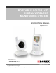
PORTABLE COLOR LCD DIGITAL WIRELESS MONITORING SYSTEM INSTRUCTION MANUAL English Version 1.0 MODELS: LW2002 Series www.lorexcctv.com Copyright © 2008 Lorex Technology Inc. Color may not be exactly as shown. Color varies by model number.
Thank you for purchasing the LW2002 Portable Digital Wireless Monitoring / Surveillance System. Lorex is committed to providing our customers with a high quality, reliable security product. http://www.lorexcctv.com Wireless Disclaimer: This product broadcasts over public airways. Digital Wireless is a secure signal, however video and audio signals may be intercepted without your consent. CAUTION RISK OF ELECTRIC SHOCK DO NOT OPEN CAUTION: TO REDUCE THE RICK OF ELECTRIC SHOCK DO NOT REMOVE COVER (OR BACK).
ENG Important Safeguards Important Safeguards In addition to the careful attention devoted to quality standards in the manufacture process of your video product, safety is a major factor in the design of every instrument. However, safety is your responsibility too. This sheet lists important information that will help to assure your enjoyment and proper use of the video product and accessory equipment. Please read them carefully before operating and using your video product. Installation 1.
Important Safeguards Service Use 13. Servicing - Do not attempt to service this video equipment yourself as opening or removing covers may expose you to dangerous voltage or other hazards. Refer all servicing to qualified service personnel. 19. Cleaning - Unplug the video product from the wall outlet before cleaning. Do not use liquid cleaners or aerosol cleaners. Use a damp cloth for cleaning. 14.
ENG General Precautions General Precautions 1. All warnings and instructions of this manual should be followed 2. Remove the plug from the outlet before cleaning. Do not use liquid aerosol detergents. Use a water dampened cloth for cleaning 3. Do not use this unit in humid or wet places 4. Keep enough space around the unit for ventilation.
Features Features Digital Wireless Technology Provides Excellent Image Quality and Clarity Interference Free, secure and private signal. Up to 450ft Wireless Transmission Range* Listen in with Exceptional Sound Clarity Safety Warning Feature Notifies You When out of Range System expandable up to 4 Cameras** * Maximum open space transmission range. The actual range is dependent upon building materials and other obstructions in path of wireless signal. ** Additional Cameras sold separately.
ENG Table of Contents Table of Contents Important Safeguards.................................................................................................................................... 3 General Precautions ..................................................................................................................................... 5 Features ......................................................................................................................................................
Getting Started Getting Started The System comes with the following components: 1 x WIRELESS RECEIVER 1 x RECEIVER CRADLE 1 x POWER ADAPTOR (FOR RECEIVER) 1 x POWER ADAPTOR(S) (FOR CAMERA) * 1 x WIRELESS CAMERA(S)* 1 x RCA VIDEO CABLE CHECK YOUR PACKAGE TO CONFIRM THAT YOU HAVE RECEIVED THE COMPLETE SYSTEM, INCLUDING ALL COMPONENTS SHOWN ABOVE. * 1 of each of the above is provided with the Camera. Please see your Product Package for the number of cameras included with your System.
ENG Wireless Receiver Wireless Receiver Front Controls 1. Receiver Antenna – Receives & Sends signals to or from the Cameras* 1 2. Power / Audio Level LEDs – The Green LED indicates the Receiver Power is ON or OFF. The Red LED’s indicate the Audio Levels (Low to High). 2 3. LCD Screen – Displays video from the Camera. 4. MENU Button – Press to Access the Receiver Menu. Press the button again to exit.
Wireless Receiver Bottom Control 10 10. Pair Button – Press the Pair button when Pairing the Receiver with a Camera. Side Controls 11. Night Light Button – Press to remotely turn Night Light ON or OFF (for the camera currently being displayed on the LCD Screen). 12. Alarm +/- Button – Press to increase or decrease the sensitivity of the audio alarm. 13. Power Button – Press to turn the Receiver ON or OFF. 11 12 13 14 15 14.
Wireless Receiver Installation Determine if you will be using the Receiver Cradle, or connecting the cables directly to the receiver before installation: 1. Place the Receiver Cradle or Receiver in a place that will have clear reception with your camera(s). 2. Plug the AC adaptor power output cable into the 9V POWER input of the Cradle or Receiver. Plug the power plug into a wall outlet or surge protector. 3.
Camera Installation Side Controls 7. Sound Alarm Trigger – Adjust the Trigger to set the Sound Alarm sensitivity. The Receiver will beep to alert the user when the sound is above a preset sound level. Adjust the side wheel to Increase or Decrease the level. 8. Camera ON/OFF Switch – Turns the Camera ON or OFF. 7 8 Camera Installation Before you install the camera, carefully plan where and how it will be positioned, and where you will route the cable that connects the camera to the power adaptor.
Installing the Camera: 1. Carefully unpack the Camera. NOTE: If you are installing Cameras that did not come with the System, please see the Pairing Camera section of this manual for details on installation. 2. Mount the camera to the wall: • Mark the position of the screw holes on the wall. • Drill holes and insert 3 screws. • Firmly attach the camera to the wall by placing the stand over the installed screws and pushing the base downwards to secure.
Viewing Mode BATTERY PACK: 1. Remove the Battery Cover off the base of the Camera. 2. Insert 4 x AA Batteries (not included) into the Battery Pack. Make sure to correctly line up the Positive (+) and Negative (-) terminals of the batteries. Place the Battery Pack cover back on. NOTE: If the Camera is plugged in with the AC Adaptor, the batteries will not be used. The batteries are intended for short term, portable Camera use only.
ENG Low Signal / No Signal Warnings When the Camera is positioned too far from the Receiver, warning messages will be displayed: LOW SIGNAL: The “Low Signal” signal appears when the receiver has One or Two bars. You will still get an image, however updating may be less frequent. NO SIGNAL: The “No Signal” message means the receiver cannot access the camera. Please reposition the camera, or check the Camera power.
Accessing Menu System Accessing Menu System Press the MENU Button on the Receiver to enter MENU System. Use the ▲▼◄► Buttons to navigate UP, Down, Left or Right in the menu, and press the OK Button to confirm a setting. Main Menu The Main Menu contains 4 submenus: 1. PAIRING – Use the Pairing menu to add camera(s) to the receiver. 2. EV – Adjusts the Brightness level of the Receiver LCD Screen. 3. POWER SAVING – Turns on the Receiver Power Save mode (when no activity on the cameras is detected). 4.
Power Saving Menu The Power Saving Menu is used to turn off the screen at a predetermined time, when there is no camera detected or connected to the Receiver. This function can be set to 1 minute, 2 minutes, 5 minutes, 10 minutes, or disabled by selecting Cancel. Setting Menu The Setting Menu contains 2 submenus: 1. A/V Out – Changes the quality of the image sent to the A/V receiving device (i.e. TV or Monitor). 2. Default – Resets all menu settings to Factory Default.
Camera Pairing Camera Pairing The System comes with camera(s) that have already been paired. These cameras will communicate with the receiver once powered on. The Pairing Function assigns each Camera to a different channel on the Wireless Receiver (up to 4 Cameras), and is necessary for configuring additional cameras. NOTE: It is highly recommended to pair the Cameras to the Receiver before permanently mounting the Cameras. 1.
7. Press the PAIR button on the back of the Camera. Once the camera has been paired, it will be immediately viewable on the Receiver Monitor. Troubleshooting If you have problems with your System, there is often a quick and simple solution. Please try the following: Problem There is no picture from a Camera. The picture is dropping There are problems with the Audio.
Appendix #1 - Receiver Specifications Appendix #1 - Receiver Specifications Receiver Receiving Frequency Range Data Rate Receiving Sensitivity Demodulation Type Resolution Viewing Angle A/V Output / Resolution Alarm Sensitivity Power Requirement Power Consumption Operating Temp Range Operating Humidity 2.400GHz~2.482GHz 1.
Appendix #3 – About Digital Wireless Technology The Digital Wireless signal transmission type used by the Lorex 2002W series is also known as FHSS – Frequency Hopping Spread Spectrum. This type of signal is highly resistant to deliberate jamming as it generates a channel hopping sequence using an algorithm generated by the receiver system. The 2.4GHz (2.400-2.