4 CHANNEL NETWORKABLE DIGITAL VIDEO RECORDER Instruction Manual English Version 1.0 MODEL: SC325000 Copyright © 2006 LOREX Technology Inc.
Thank you for purchasing the 4 Channel Networkable Digital Video Recorder. Sentinel CCTV is committed to providing our customers with a high quality, reliable security product. This DVR product has High quality recording using advanced MJPEG video compression (5~20Kbyte/ frame), and supports 2 disk drives (1 internal/1 removable). It supports multiple viewing modes and video motion detection. This system also includes free access to a DDNS Server for remote viewing. .
Important Safeguards Important Safeguards In addition to the careful attention devoted to quality standards in the manufacture process of your video product, safety is a major factor in the design of every instrument. However, safety is your responsibility too. This sheet lists important information that will help to assure your enjoyment and proper use of the video product and accessory equipment. Please read them carefully before operating and using your video product. Installation 1.
Important Safeguards Service Use 13. Servicing - Do not attempt to service this video equipment yourself as opening or removing covers may expose you to dangerous voltage or other hazards. Refer all servicing to qualified service personnel. 19. Cleaning - Unplug the video product from the wall outlet before cleaning. Do not use liquid cleaners or aerosol cleaners. Use a damp cloth for cleaning. 14.
General Precautions NOTE This equipment has been certified and found to comply with the limits regulated by FCC, EMC, and LVD. Therefore, it is designated to provide reasonable protection against interference and will not cause interference with other appliance usage.
DVR Features DVR Features • High quality recording using advanced MJPEG video compression (5~20Kbyte/frame) • Supports 2 disk drives (1 internal/1 removable) • Remote Control or Main Panel operation • Password Security Protected • Multiple Viewing modes: Quad, Full Screen • Video motion detection • Audio recording • Free DDNS Service Included NetViewer Software • View and Record from your PC - Connect your DVR to your Network • Minimum System Requirements: Windows XP, Pentium 4 processor with 256MB RAM v
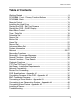
Table of Contents Table of Contents IGetting Started ......................................................................................... 9 SC325000 - Front - Primary Function Buttons ........................................ 10 SC325000 - Back .................................................................................... 12 Remote Control ....................................................................................... 13 Installing the Hard Drive ..........................................
Table of Contents 8
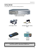
Getting Started Getting Started The SC325000 system comes with the following components: 4 CHANNEL NETWORKABLE DVR (Hard Drive NOT Included) Power Supply - 12V 5A Remote Control (with Batteries) Quadruple BNC Video Looping Cable NetViewer Software CHECK YOUR PACKAGE TO CONFIRM THAT YOU HAVE RECEIVED THE COMPLETE SYSTEM, INCLUDING ALL COMPONENTS SHOWN ABOVE.
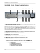
SC325000 - Front - Primary Function Buttons SC325000 - Front - Primary Function Buttons 1 2 10 3 4 5 6 7 8 9 11 12 13 14 15 16 1. REMOVABLE HARD DRIVE BAY - Mounting location for a REMOVABLE HARD DRIVE. See Page 14 for Hard Drive Installation instructions. NOTE: This DVR allows for the connection of 2 Hard Drives at 300GB each. For ease of use, a drive can be connected using the REMOVABLE HARD DRIVE BAY. Please see instructions on page 14 for further details.
SC325000 - Front - Primary Function Buttons 1 2 10 3 4 5 6 7 8 9 11 12 13 14 15 16 8. MENU BUTTON - Displays the on screen MENU. For details on MENU options, see page 18. 9.
SC325000 - Back SC325000 - Back 1 6 2 3 4 5 7 8 1. VIDEO OUT - VIDEO Output connections to a MONITOR or DVR 2. VIDEO IN (CH1-CH4) - Channel 1-4 VIDEO INPUTS (for CAMERA or SERVATION SYSTEM connectivity) 3. AUDIO OUT - Port for connecting AUDIO OUT from the DVR to another device 4. AUDIO IN (CH1-CH4) - Channel 1-4 AUDIO INPUTS (from CAMERA or DVR) 5. POWER SWITCH - Turn the DVR unit ON/OFF 6. ETHERNET PORT - Used to connect the DVR to a ROUTER for NETWORK CONTROL 7.
Remote Control Remote Control Listed below is a quick reference for use of the Remote Control. For more details on specific remote control features, refer to the Front Panel features. 1. REC - Initiates recording 2. /CH1 - Up in MENU Mode / Change to CH1 3. ONE FRM - Advance one frame in playback 4. /CH4 - Left in MENU Mode / Change to CH4 5. QUAD/ENTER - Change to QUAD Mode / Enter in MENU Mode 6. EVENT - Enter EVENT Search Mode 1. 2. 10. 3. 4. 5. 6. 11. 12. 13. 7. 7.
Installing the Hard Drive Installing the Hard Drive The Hard Drive serves the same purpose in a DVR as a video cassette does in a VCR. Please follow the steps carefully in order to ensure proper installation. The compartment located on the front panel of the DVR is the removable Cartridge Casing in which you insert the Hard Drive. The various parts of the Cartridge Casing are labeled for your reference. STEP 1: Remove the Cartridge Casing from the DVR. • Lift the Handle and pull towards you.
Installing the Hard Drive STEP 4: Secure the Hard Drive in the Casing • Use screws and tighten them, positioning the Hard Drive into place. This step is optional, but it is recommended. Position Hard Drive and secure with provided screws STEP 5: Slide the top Cover over the Cartridge Casing • Slide the Cover forward over the Cartridge Case. Ensure it is secured in place over the release latch.
Starting the DVR - Self Test Screens Starting the DVR - Self Test Screens Once the DVR has been connected and powered on, the following self-test screens will appear: NOTE: This unit does NOT include a Hard Drive. LOREX STANDALONE DVR [ V #.## ] SYSTEM START: The first loading screen indicates the DVR type and firmware version as [ V #.## ] MASTER HDD *************** SLAVE HDD ........... NOT INSTALLED AUDIO OK HARD DRIVE DETECTION: The second loading screen detects the MASTER and SLAVE HARD DRIVES.
Starting the DVR - QUAD Display Starting the DVR - QUAD Display After the system self-tests have been completed, the DVR will switch to the CAMERA viewing screens (in QUAD MODE) with the following information displayed on screen: • ALARM [----]: Shows CAMERAS in ALARM mode • CH1-CH4: Camera title indicators • USED #% [M]: Amount of HARD DRIVE used (in GB) z [M] indicates MASTER HARD DRIVE z [S] indicates SLAVE HARD DRIVE • MM/DD/YYYY - HH:MM:SS: The current system date and time.
Main Menu Control Main Menu Control Enter the MENU screen by pressing the MENU button. Scroll through the 9 options by pressing the UP and DOWN buttons. To enter a sub-menu, navigate to the option and press the button. To exit a SUBMENU, press the MENU button, which takes you back to the MAIN MENU. To exit the MAIN MENU, press the MENU button.
Time / Date Set Time / Date Set This submenu allows you to change the TIME and DATE displayed on the monitor (On Screen Display), and recorded on the DVR. 1. DATE FORMAT - Display the DATE FORMAT on the monitor screen. Navigate using the buttons, and press the button to set the date format. Available options include: TIME/DATE • YYYY/MM/DD DATE FORMAT MM/DD/YYYY .. DATE/TIME SET • MM/DD/YYYY • DD/MM/YYYY [ ]MOVE [ ]SELECT []EXIT 2. DATE/TIME SET- Changes the date and time for the DVR.
Schedule Set Schedule Set This submenu allows you to set an automatic recording schedule for the DVR 1. SCHEDULE - Sets the scheduled recording to ON/ OFF. Navigate to this option using the buttons, and press the button to change the option. TIME/DATE 2. RECORD FPS - Sets the recording speed in FPS (Frames Per Second). Navigate to this option using the buttons, and press the button to change the option to one of the following settings: 1 / 2 / 3 / 4/ 5 / 7 / 10 / 15 / 30.
Sensor Set Sensor Set This submenu allows you to change the settings for a separate sensor device (such as a stand-alone Motion Sensor, or Door/Window Sensor). These sensors are installed on the ALARM BLOCK (see page 41 for Alarm Block Configuration). SENSOR 1. SENSOR RECORD DURATION - Sets the length of time for the recording once a sensor input has been detected (i.e. If Motion is detected, the DVR will start recording, and will continue recording for 10 seconds).
Alarm Set Alarm Set This submenu allows you to set the Alarm (based on Sensor or Motion input). When a Sensor event or Motion is detected, an Alarm EVENT will be triggered and an indicator will be displayed on the top left side of the monitor screen (see the QUAD screen diagram on the bottom of page 29). 1. DURATION - Sets the length of time an ALARM message is displayed on the monitor.
Record Set Record Set This submenu controls the RECORDING settings for the DVR. 1. RECORD MODE - Configures the recording type. buttons, and Navigate to this option using the press the button to change the option: RECORD • EACH - In EACH mode, the system records the video images from the 4 cameras separately. Each camera recording can be played back individually (in full screen) using the 1-4 buttons.
Advanced Menu Set Advanced Menu Set You will need to enter the master password (111111) to enter the Advanced Menu settings 1. CHANGE PASSWORD - Allows you to change the password for the DVR. Navigate to this option buttons, and press the button to using the access the PASSWORD menu: [ PASSWORD ] • Current Password - Default Master Password is 111111 • New Password: Enter a new password • Confirm Password: Confirm the new password 2. PASSWORD ENABLE - Sets the Password to ON/ OFF for Recording.
System Information System Information This submenu displays information about the Hard Drives in the DVR. 1. HDD CAP DISPLAY - Sets the Hard Drive Capacity on screen display to ON/OFF. Navigate buttons, and press to this option using the the button to change the option to either Y or N. 1. HDD SUMMARY - Shows a summary of Hard Drive usage for the Master Hard Drive and Slave Hard Drive (if installed). All figures in the table are displayed in GB.
Network Network This submenu allows you to change the configurations for the NETWORK. This DVR supports a Dynamic IP with DIPS (Dynamic IP Service). Many high speed customers do not have a static IP address - instead the ADSL provider leases a Dynamic IP (the IP address changes periodically). The DIPS server allows you to access your DVR regardless of Dynamic changes. 1. CLIENT ACCESS ENABLE - Allows access and control to the DVR using the Client Program (through the Network) if set to YES.
Network Network 5. DDNS - The DDNS Value will automatically be completed when GET DDNS is set to YES. To manually set this value, navigate to this option using the buttons, and press the button to access the DDNS Submenu. Use the keys to change the values, and press the key to accept the change. 6. DNS - The DNS Value will automatically be completed when GET DNS AUTOMATICALLY is set to YES.
Recording Functions Recording Functions The SC325000 DVR has 4 available recording types: Manual, Schedule, Motion or Sensor. • Motion: Recording starts when Motion is detected from a Camera input. Motion Recording is configured through the Motion Menu options. Refer to Page 21 for more details. • Sensor: Recording starts when the system detects a Sensor Input at the Alarm Block (i.e. Door Sensor, Window Sensor or Independent Motion Sensor).
Recording - On screen Messages Recording - On screen Messages • ALARM: Displays the current Alarm Configuration for all channels. In the above image, 1 indicates that Channel 1 is in ALARM, Channel 2 is NOT Configured for Alarm mode, and Channels 3 and 4 are NOT in ALARM mode. • USED/SIZE: Displays the amount of Hard Drive space used, and the Total Hard Drive space available • KEY IS LOCKED - ENTER PASSWORD: Indicates that the system is LOCKED mode (Configured through the MENU).
Search Functions - Event Search Search Functions - Event Search Press the EVENT button on the main control panel to access the Recorded Events by: • Total Event - Displays all recorded event types • Scheduled Event - Displays Scheduled recording • Sensor Event - Displays Sensor event recording • Motion Event - Displays Motion event recording • Manual Event - Displays Manual event recording Navigate using the buttons, and press the EVENT SEARCH MASTER HDD TOTAL EVENT SCHEDULE EVENT SENSOR EVENT MOTION EVE
Search Functions - Time Search Search Functions - Time Search Press the TIME button on the main control panel to access the Recorded Events by time.
PTZ (Pan/Tilt/Zoom) Control PTZ (Pan/Tilt/Zoom) Control The SC325000 DVR supports PTZ Mode, however this will only work with PTZ type cameras Press the SLOW button on the front panel of the DVR to enter PTZ Mode ] The following buttons are used to Control a camera in PTZ mode: • SLOW Button: Enter / Exit PTZ Mode • CH1 Button: UP Mode - moves the camera UP • CH2 Button: RIGHT Mode - moves the camera RIGHT • CH3 Button: DOWN Mode - moves the camera DOWN • CH4 Button: LEFT Mode - moves the camera LEFT • ON
NetViewer - Installation Requirements NetViewer - Installation Requirements The NetViewer software (included with the DVR) has the following installation requirements. Minimum System Requirements: Operating System Windows 2000 Windows XP Home Edition Windows XP Professional Processor .Pentium 4 - 1.5 GHz Processor (or equivalent) Memory 256 MB RAM Hard Drive 50 MB - Installation space required * Additional Hard Drive space required for recording.
Network Connectivity Network Connectivity The SC325000 DVR can be remotely controlled using your existing network and the provided NetViewer software. 1. Connect the DVR to the Router using the supplied Ethernet Cable. Power the Observation unit on. DVR NOTE: The DVR must be connected to the router prior to powering on the system. This allows the system to communicate on your network 2. Set up a web account at http:// dips.dipserv.com/.
Router Port Forwarding Router Port Forwarding You will need to enable port forwarding on your Router to allow for external communications with your DVR. Enable port forwarding on: • Port 14337 • Port 14338 Computers, DVR’s, and other devices inside your network can only communicate directly with each other within the internal network. Computers and systems outside your network cannot directly communicate with these devices.
Router Port Forwarding 36
DVR Specifications - Appendix #1 DVR Specifications - Appendix #1 Video Input / Video Output 4 Channel Input / 2 Channel Output Video Input Standard NTSC / PAL Monitoring Resolution (NTSC / PAL) 640 x 480 Pixels (NTSC) 640 x 576 Pixels (PAL) Recording Resolution (NTSC / PAL) 640 x 224 Pixels (NTSC) 640 x 272 Pixels (PAL) Display Frame Rate (NTSC / PAL) 120 FPS (QUAD) / 30 FPS (Each) (NTSC) 100 FPS (QUAD) / 25 FPS (Each) (PAL) Recording Frame Rate (NTSC / PAL) 30 FPS (QUAD) / 7.
Connecting Cameras to the DVR - Appendix #2 Connecting Cameras to the DVR - Appendix #2 The SC325000 DVR can be used up to 4 BNC Cameras (not included) DVR 4 BNC CAMERAS BNC Connected Cameras BNC connected cameras are not included with the DVR, however can be ordered online at www.sentinelcctv.com BNC Cameras have several cables and receive power from a wall outlet. Connecting BNC Cameras to the SC325000 DVR requires the use of the included BNC to RCA Adaptors 1.
Connecting a Slave Monitor - Appendix #3 Connecting a Slave Monitor - Appendix #3 Connections to a Slave Monitor (not included) can be made through the VIDEO OUT ports on the back of the DVR DVR SLAVE MONITOR (Not Included) A Slave Monitor is used as a View Only device. A Slave Monitor can only display camera data as it is shown on-screen on the DVR. Specific controls for the DVR are configured through the Menu Options 1.
Connecting to an Observation System - Appendix #4 Connecting to an Observation System - Appendix #4 The SC325000 DVR can be used with an Observation System (not included). OBSERVATION SYSTEM DVR NOTE: If you are using an Observation System, the DIN Type Cameras should be connected to the DIN ports on the System, and Looping Video BNC should be connected between the DVR and Observation System. 1. Attach the BNC to RCA (Male to Female) adapters on the BNC CH1-CH4 found on the DVR. 2.
Connecting Alarm Device - Appendix #5 Connecting Alarm Device - Appendix #5 Alarm controls are enabled through the Menu system on the DVR. Additional alarm devices can be connected to the system (Motion Sensors, Door/Window Sensors). DVR SENSOR A motion detection or sensor unit can be used to send a signal to the DVR to begin camera viewing on the matching Video Channel (when enabled in the MENU/ALARM SET MODE) • Example: A Window sensor unit has been installed on Alarm Block port #1.
Troubleshooting Troubleshooting When a malfunction occurs, it may not be serious and can be corrected easily. The following describes the most common problems and solutions.
Troubleshooting • Check the CAMERA connections to the DVR (Audio and Video) • Check that the monitor being used has sound capabilities • Disconnect and reconnect the cable at the DVR and at the Camera • Try moving the camera to another channel or use another cable 43
It’s all on the web Product Information Specification Sheets User Manuals Software Upgrades Quick Start Guides Firmware Upgrades VISIT www.sentinelcctv.com www.sentinelcctv.com LOREX Technology Inc.