Instruction Manual SC21FD3044-161 English Version 2.0 21” FLAT SCREEN CRT/DVR COMBO Copyright © 2006 LOREX Technology Inc.
Thank you for purchasing the 21” Flat Screen CRT / DVR Combo. This unique and innovative system provides a complete security package, combining a commercial grade 4 channel Digital Video Recorder (DVR) with a 21” Flat screen CRT monitor. To learn more about this 21” Flat screen CRT / DVR Combo Observation system and about our complete range of accessory products, please visit our website at: www.sentinelcctv.com CAUTION RISK OF ELECTRIC SHOCK. DO NOT OPEN.
NOTE: This equipment has been certified and found to comply with the limits regulated by FCC, EMC and LVD. Therefore, it is designed to provide reasonable protection against interference and will not cause interference with other appliance usage. However, it is imperative that user follows this manual's guidelines to avoid improper usage which may result in damage to the unit, electrical shock and fire hazard or injury.
CONTENTS 1 GENERAL PRECAUTIONS .................................................................................1 2 CAUTIONS AND FEATURES ..............................................................................2 2.1 2.2 2.3 3 FEATURES 2 CAUTIONS 3 NETVIEWER SOFTWARE INSTALLATION 3 SYSTEM INCLUDES ...........................................................................................4 4 GETTING STARTED...........................................................................................
17 RECORDING TIME (IN HOURS).......................................................................30 18 RECORDING TIME (IN GIGABYTES PER HOUR) ...........................................31 19 INSTALLING THE HDD .....................................................................................32 20 TECHNICAL SPECIFICATIONS ........................................................................35 21 TROUBLESHOOTING .................................................................................
1 GENERAL PRECAUTIONS 1. Read Instructions: All of the safety and operating instructions should be read and understood before the product is used. 2. Retain Instructions: The safety and operating instructions should be retained for future reference. 3. Heed Warnings: All warnings on the product and the instruction manual should be followed. 4. Follow Instructions: All operating and use instructions should be followed for optimal performance 5.
2 2.
2.2 CAUTIONS 1 All the warnings and instructions of this manual should be followed 2 Remove the plug from the outlet before cleaning. Do not use liquid aerosol detergents. Use water damped cloth for cleaning 3 Do not use this unit in very humid and wet places 4 Keep enough space around the unit for ventilation. Slots and openings of the cabinet should not be blocked.
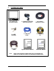
3 SYSTEM INCLUDES REC PLAY TIMER ALARM HDD FULL POWER USB CH3 CH4 Q1/Q2 SEQ PIP/POP MENU SEARCH EVENT CH1 COPY CH2 PAN/TILT ALRS CH5 CH6 VOLUME CH7 CH8 A-SEL TALK 21” Flat Screen CRT/DVR Combo 2 x HDD Cartridge AC Power Cable NOTE: STAND-BY 4 x Cameras (SG7518) with camera stand 1 x Ethernet Cable System Owners Manual 4 x Camera Extension Cables 1 x Net Viewer CD Netviewer Manual CHECK YOUR PACKAGE TO MAKE SURE THAT YOU RECEIVED THE COMPLETE SYSTEM, INCLUDING THE COMPON
4 GETTING STARTED 1 Connect the AC Power Cord to the AC Input of the 21” Flat Screen CRT / DVR Combo and plug into an electrical outlet. Connect the cameras into the camera inputs (BNC or DIN) found on the back of the Unit. Plug one end of the Ethernet cable into the Ethernet Port of the 21” Flat Screen CRT / DVR Combo and the other end into an open Ethernet port of the router. Turn the Main Power Switch ON. When power is applied, the unit will go through an internal diagnostic test.
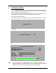
After the unit has completed its internal diagnostic test, the network information will be displayed (for a short period of time). (See below) *** NETWORK INFORMATION *** MAC ADDRESS : XX XX XX XX XX XX IP ADDRESS : 192 . 168 . 001 . 100 SUBNET MASK : 255 . 255 . 255 . 000 GATEWAY : 192 . 168 . 001 . 001 PORT : 5000 The unit will then display the video image(s) from the camera.
5 DESCRIPTION OF PARTS AND FUNCTION – FRONT PANEL STAND BY LED PLAY REC TIMER ALARM HDD FULL POW ER USB CH1 CH2 CH3 CH4 Q1/Q2 SEQ PIP/POP MENU SEARCH EVENT COPY WTMK PAN/TILT ALRS USB PORT CH5 CH6 VOLUME CH7 CH8 A-SEL TALK STAND-BY REC REC STOP JOG SHUTTLE CHANNEL / ARROW BUTTON MIC ↵ CH1 CH2 CH3 SEQ BUTTON QUAD 1/2 BUTTON CH4 CH5 CH8 AUDIO SEL BUTTON TALK BUTTON Q1/Q2 SEQ PIP/POP MENU VOLUME SEAR CH EVENT COPY W TM K WTMK A-SEL TALK VOLUME BUTTON RE C REC
2 QUAD BUTTON Pressing this button goes to Quad viewing mode, either Page A (Q1) or Page B (Q2). 3 SEQ BUTTON Used to automatically sequence between all camera locations in full screen view. Press SEQ again to stop sequential viewing. Sequence settings are programmable via the Menu. 4 PIP/POP BUTTON PIP allows you to view two camera locations simultaneously, one being the main channel, the other being viewed as a sub-picture.
By pressing and holding this button the user has the ability to talk to a specific camera location. This button must be pressed the entire time, while talking. To listen to the camera location, release the Talk button. 9 SEARCH / EVENT BUTTON a) SEARCH : Pressing this button brings up the Search menu, which allows you to quickly find recordings. b) EVENT : Pressing this button brings up a list of up to 1,000 Events, including Power, Loss and Alarms.
13 REW BUTTON Press this button to begin high-speed reverse playback during the playback. 14 PLAY / PAUSE BUTTON a) Initiates video Playback. b) PAUSE : Press this button to pause video in playback. 15 FF BUTTON Press this button to begin high-speed forward playback during the playback. 16 REC / REC STOP BUTTON REC: Press this button to start manual recording. REC STOP: Pressing this button for more than 3 seconds will stop recording. 17 STAND_BY BUTTON Turns the monitor screen ON/OFF.
e) HDD FULL: If the OVERWRITE menu is set up, the LED will not blink in any case. The LED blinks if the HDD has less than 1GB of storage space, and remains ON when the HDD is FULL. f) 21 POWER: This LED will be illuminated when POWER is applied to the unit. USB PORT Connect a USB memory stick to back-up the recorded data. Note: The amount of data that can be transferred based on the capacity of the memory stick.
6 DESCRIPTION OF PARTS AND FUNCTION – BACK PANEL 11 2 10 CH1 CH3 CH5 CH7 CH2 CH4 CH6 CH8 CH1 CH3 CH5 CH7 CH2 CH4 CH6 CH8 9 8 7 ETHERNET USB RS-232 ALARM OUT WARNING OUT POWER + - VIDEO INPUT + - + - + - + - + - + - + MONITOR OUT VIDEO IDE-SUB SLAVE OUT AUDIO INPUT 1 5 2 6 3 7 4 8 AUDIO AC 12 1 3 4 5 6 1 BNC Camera Inputs - Channel 1-8 camera inputs (for cameras with BNC Video outputs) 2 6 Pin DIN Camera Inputs - Channel 1-8 Camera inputs (for cameras with 6
7 MAIN MENU CONTROL MAIN 1.TIME/DATE SET DISPLAY TIME DATE DATE FORMAT 2. SEQUENCE SET QUAD A CH1 : QUAD B CH5 : 3.TITLE SET DISPLAY CH1 : : CH8 ALARM CH1 : : 4.ALARM SET CH8 5.MOTION SET MOTION CHANNEL SENSITIVITY AREA 6.
7. SYSTEM (Ⅱ ) HDD INFO DISP RS232 BAUD RATE PASSWORD SET NETWORK(TCP/IP) USER ID/PASSWORD GUEST PASSWORD BAND WIDTH IP ADDR SUB NET GATEWAY PORT 8.HDD / REC SET REC QUALITY REC RESOLUTION REC SPEED USB REC LIMIT HDD CLEAR ALL HDD OVERWRITE HDD SLAVE 9.ALARM REC SET ALARM REC PRE ALARM REC REC QUALITY REC SPEED REC DURATION 10.SCHEDULE REC SET SCHEDULE REC REC SETTTING 11.MONITOR SET CONTRAST BRIGHT COLOR TINT SHARPNESS 12.FIRMWARE UPGRADE FIRMWARE UPGRADE 13.
Enter the MENU screen by pressing the MENU button. Scroll through the 12 options by pressing the UP and DOWN buttons. To enter a sub-menu, press the Enter button where the highlighted scroll bar is located. To exit the Main Menu, scroll down to the Exit option and press the Enter button. NOTE: In sub menu of the Main Menu, you can exit the Menu mode by selecting Exit, or you can return to the Main Menu by selecting Return. NOTE: The Menu is exited automatically after 60 sec of inactivity. 7.
NOTE: Some alternative brand PIR motion sensors have a default setting of N.C (normally closed). In order to activate the alarm on such a PIR motion sensor, change the setting to N.C 7.5 MOTION SET This submenu allows you to enable / disable the Pixel-based Motion Detection function by channel and set its Sensitivity level. a) MOTION : Selecting [OFF] disables the Pixel-based Motion Detection function.
h) DEFAULT SET : Selecting [Y] resets all programmed settings back to the default factory settings (except for the time & date). NOTE: If you perform a DEFAULT SET, the programmed data you have entered for the DDNS will be automatically deleted. You need to set the data again. 7.7 SYSTEM SET (II) This sub-menu allows you to configure various preferences on the system, related to DVR settings. a) HDD INFO DISP : Sets the display settings for information on the HDD status.
a) REC QUALITY : Sets the quality level of recording. Available settings are : Basic, Normal, High and Best. NOTE: Higher quality recording consumes more memory on your HDD. Please refer to RECORDING TIME (IN HOURS) on page 30. b) REC RESOLUTION c) REC SPEED : Allows you to set the Images Per Second for recording. Available IPS settings are: 1, 2, 3, 5, 10, 15, 30 & 60. The speed of 60 IPS is also known as “Real Time”.
[ONCE] - Recording will be carried out one time, according to the schedule. b) N0-N7 : Total 8 REC can be set up from N0 to N7. Each Schedule REC can control Start TIME/DATE, End TIME/DATE and REC Quality as well as REC Speed can be set up in this mode. NOTE: When SCHEDULE REC is set up, the recording time should not be overlapped from one scheduled recording to another. If it is overlapping this will result in a loss in recorded activity and the schedule may be ignored.
d) USER PASSWORD : Put the Password that you have set with the DDNS server. As the maximum character available with this unit will be 8 digits, the User Name should not exceeding 8 characters and your special attention required when you are setting with the DDNS server. e) ROUTER : If you are using the ROUTER for the internet connection, you could set it “YES”. Otherwise select “NO”. NOTE: When registering for the DDNS service, you cannot exceed 8 characters for the user name, password, or domain name.
8 PLAYBACK SEARCH The DVR/MONITOR allows you to easily find sections of recorded video using the Search feature. Press the SEARCH button to access the “PLAYBACK SEARCH SET” menu. [ PLAYBACK SEARCH SET ] PB:[ MASTER ] REC:[ MASTER ] 1. LAST RECORD 2. FULL LIST 3. ALARM LIST 4. TIME SEARCH 5. EXIT (1) LAST RECORD: Plays the most recent recording. (2) FULL LIST: Shows a listing of all recorded video on the HDD, sorted by time. (3) ALARM LIST: Shows a listing of all recorded video triggered by an Alarm.
9 PLAYBACK OPTION When the PLAY button is pressed, one of the Playback Search menus will appear. The Playback menu that appears upon pressing PLAY depends on the Search option that was last used. For example, if the last Search option used was a Time Search, then pressing PLAY will bring up the Playback Time Search. If the last Search option utilized was a Last Record, then pressing play will simply play the most recent recording. 9.
10 PAN/TILT ZOOM The DVR/MONITOR is equipped with a built-in Pan/Tilt Zoom feature, which is only available when used in conjunction with a compatible Pan/Tilt Dome camera. The Pan/Tilt Zoom feature supports “Pelco D” protocol. To access and operate the PTZ feature, follow these instructions: 1 Connect a compatible Pan/Tilt Zoom Dome camera to the CH 1 camera input.
11 REMOTE CONTROL Features of the Remote Control. For more details on specific remote control features, refer to the Monitor features KEY FUNCTION DESCRIPTION SLEEP Mode On/Off. MENU Brings up the Main Menu. 1-8 Allows user to select individual cameras FRZ 1/5 Freezes the Channel 1/5 screen FRZ 2/6 Freezes the Channel 2/6 screen FRZ 3/7 Freezes the Channel 3/7 screen FRZ 4/8 Freezes the Channel 4/8 screen PAN/TILT Enters Pan/Tilt Zoom mode.
12 CAMERA (DIN Connector) INSTALLATION Connect the camera to the CAMERA INPUT on the rear panel of the system.
13 CAMERA (BNC Connection) INSTALLATION Connect the camera to the CAMERA INPUT on the rear panel of the system.
14 MONITOR AND STANDARD VCR INSTALLATION Connect the camera to the CAMERA INPUT on the rear panel of the system CH1 CH3 CH5 CH7 CH2 CH4 CH6 CH8 CH1 CH3 CH5 CH7 CH2 CH4 CH6 CH8 USB ETHERNET RS-232 ALARM OUT WARNING OUT POWER + - VIDEO INPUT + - + - + - + - + - + - + MONITOR OUT VIDEO 1 5 2 6 3 7 4 8 AUDIO AC VIDEO INPUT AUDIO INPUT VCR AUDIO INPUT VIDEO INPUT MONITOR 27 IDE-SUB SLAVE OUT AUDIO INPUT
15 ETHERNET (NETWORK), EXTERNAL ALARM DEVICE INSTALLATION INTERNET SENSOR CH1 CH3 CH5 CH7 CH2 CH4 CH6 CH8 CH1 CH3 CH5 CH7 CH2 CH4 CH6 CH8 ETHERNET USB RS-232 ALARM OUT WARNING OUT POWER + - VIDEO INPUT + - + - + - + - + - + - + MONITOR OUT VIDEO 1 5 2 6 3 7 4 8 AUDIO AC 28 IDE-SUB SLAVE OUT AUDIO INPUT
16 NETWORK IMAGE SIZE AND SPEED 720 X 240 NOTE: 360 X 240 IMAGE SIZE IPS IMAGE SIZE IPS BASIC 16K ~ 17K 10 ~ 15 10K ~ 11K 23 ~ 28 NORMAL 19K ~ 20K 09 ~14 11K ~ 12K 23 ~28 HIGH 23K ~ 24K 09 ~ 14 14K ~ 15K 15 ~ 20 BEST 32K ~ 33K 09 ~ 14 19K ~ 20K 10 ~ 15 The demanding volume of HDD can be different in depending on the displayed picture.
17 RECORDING TIME (IN HOURS) BASED ON 160 GB H.D.D.
18 RECORDING TIME (IN GIGABYTES PER HOUR) 720 X 240 BASIC NORMAL HIGH BEST 01 IPS 0.056GB/H 0.064GB/H 0.078GB/H 0.106GB/H 02 IPS 0.112GB/H 0.128GB/H 0.156GB/H 0.211GB/H 03 IPS 0.169GB/H 0.192GB/H 0.233GB/H 0.317GB/H 05 IPS 0.28GB/H 0.321GB/H 0.389GB/H 0.528GB/H 10 IPS 0.562GB/H 0.642GB/H 0.778GB/H 1.06GB/H 15 IPS 0.843GB/H 0.962GB/H 1.17GB/H 1.59GB/H 30 IPS 1.69GB/H 1.92GB/H 2.33GB/H 3.17GB/H 60 IPS 3.37GB/H 3.85GB/H 4.67GB/H 6.
19 INSTALLING THE HDD NOTE: The HDD serves the same purpose in the DVR/Monitor as a video cassette does in a VCR. However, installing the HDD is a bit more complicated. Please follow the next steps carefully in order to ensure proper installation. The compartment located on the front panel of the DVR/MONITOR is the removable Cartridge Casing in which you insert the HDD. The various parts of the Cartridge Casing are labeled for your reference. 1 Remove the Cartridge Casing from the DVR.
NOTE: The 4 Pin connection is the DC Power cable, and the wider cable is the standard Hard Drive IDE type connection 4 Secure the HDD in the Casing (optional) Use screws and tighten them, positioning the HDD into place. This step is optional, but it is recommended. 5 Slide the top Cover over the Cartridge Casing Slide the Cover forward over the Cartridge Case. Ensure it is secured in place over the release latch.
A (locked) B (u 8 If you need to unlock the cabinet, turn the key counter-clockwise from the position shown above.
20 TECHNICAL SPECIFICATIONS DVR Recording Speed : HDD Capacity : Recording Video Quality : 60 Fields / Sec. 400GB (Max.
21 TROUBLESHOOTING If the system does not function properly, please check the following points. PROBLEM REMEDY Too dark or bright picture Readjust the CONTRAST or BRIGHTNESS controls Poor picture quality Clean the camera lens. Readjust the CONTRAST or BRIGHTNESS controls. Picture but no sound Adjust the volume Picture, but no control Reset the system by turning off the main power and unplugging the system. Turn the system on again after 30 seconds.
22 CARE AND MAINTENANCE Please follow these instructions to ensure proper care and maintenance of this system Keep your monitor and camera dry. If it gets wet, wipe it dry immediately. Use and store your unit in normal temperature environment. Extreme temperatures can shorten the life of the electronic devices. Handle the monitor carefully. Dropping it can cause serious damage to the unit. Occasionally clean the unit with a damp cloth to keep it looking new.
It’s all on the web Product Information Specification Sheets User Manuals Software Upgrades Quick Start Guides F.A.Qs VISIT www.sentinelcctv.com www.setinelcctv.com Strategic Vista International Inc.