DIGITAL VIDEO CAPTURE CARD Instruction Manual English Version 2.0 MODEL: QLR-0440 Series www.lorexcctv.com Copyright © 2008 Lorex Technology Inc.
Under the copyright laws, neither the documentation nor the software may be copied, photocopied, reproduced, translated, or reduced to any electronic medium or machine-readable form, in whole or part without the prior written consent of Lorex Technology Inc., except in the manner described in the documentation. © Copyright 2008 Lorex Technology Inc 300 Alden Road Markham, Ontario L3R 4C1 CANADA All rights reserved. Printed in Canada. THIS DEVICE COMPLIES WITH PART 15 OF THE FCC RULES.
■ Important Safety Instructions 1) Read & Retain Instructions All the safety and operating instructions should be read before the appliance is operated. The safety and operating instructions should be retained for future reference. 2) Heed Warnings All warnings on the product and in the operating instructions should be adhered to. 3) Follow Instructions All operating and use instructions should be followed. 4) Cleaning Unplug this product from the wall outlet before cleaning.
Table of Contents SECTION 1 - PRODUCT INFORMATION ...................................................................................................... 5 Introduction: ............................................................................................................................................. 5 Features:.................................................................................................................................................. 5 Specifications:..........................
SECTION 1 - PRODUCT INFORMATION Introduction: Thank you for purchasing this high quality video product. The QLR DVR is a Professional Video Capture system with many advanced features offering a cost effective PC based surveillance solution. This section is designed to help get you better acquainted with the QLR system before proceeding with the installation.
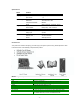
Specifications: Model Video Display Recording Playback Monitor Control Network Others QLR440 Input Speed Split Screen Speed Resolution Compression Method Mode Display Search Mode Output Sensor Input Relay Input Transmission Speed Remote View Media O/S 4 Channel RCA NTSC/PAL 30 fps (4ch) max 1, 4 30 fps (4ch) max 320 x 240, 640 x 480 MPEG 4 Motion Detection, Schedule, Sensor 1, 4 Data (Event), Time, Channel N/A 4 points 2 points Real-Time via Client Software Static/Dynamic IP Windows 98SE/ME/XP/2000 Out
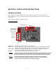
SECTION 2 - INSTALLATION INSTRUCTIONS Hardware Installation Before installing the VISTAPRO software, you must first connect the 4 Port PCI card and optional Alarm I/O Board (ACC-ALM) into your PC. The 4 Port PCI card has 4 Video inputs, allowing you to connect up to 4 cameras to your system. The connections and board lay out are shown below.
Installation Precautions: Installing the 4 Port PCI card requires some degree of technical aptitude. If you have no previous experience in opening up a computer and inserting hardware, it is advisable for you to seek assistance from a more qualified individual before proceeding. Also note that in order for the watchdog feature to function, a connection will be required to the Reset Pin of the PC Motherboard. If this Pin connection is not known, please consult the motherboards installation manual.
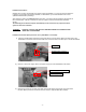
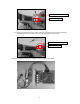
Socket for PC Power On Control PC Power Pin Cable 4) Insert the PC Reset Pin connector (yellow cable) to the socket shown for PC Reset Control of the VISTAPRO 4 and I/O Alarm block. (Device for Auto-Rebooting Watchdog function) Socket for PC Reset Control PC Reset Pin Cable Below is the complete picture of the VISTAPRO 4 and connected I/O Alarm Block.
5) Connect the PC Power Supply cable to the Power Supply connector for the VISTAPRO Main Board. (This is only required if powering cameras directly from the outputs on the back of the card or if using the ACC-1200 accessory module.) Power Supply Cable of PC VISTAPRO 4 Power Supply Cable 6) Connect the other side of PC Power Pin connection cable (red cable), from the I/O Alarm board, to the Power Pin on the PC main-board.
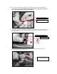
8) Insert one side of PC Reset Pin connection cable (yellow cable) from the I/O Alarm board to the Reset Pin on the PC main board. (Required for Watchdog Function) Alarm I/O Reset Pin Cable PC Main-board Reset Pin 9) Connect the other side of PC Reset Pin connection cable (yellow cable) with the Reset Switch connection cable on the front of PC case. (Required for Watchdog function) VISTAPRO PC Reset Pin Cable Reset Switch cable connector from PC Front case 10) Close the PC case cover.
11) Insert all camera connections. Camera4 (Ch4) Camera3 (Ch3) Camera2 (Ch2) Camera1 (Ch1) DC +12V (Camera1~4)* 12) Now you have successfully installed the VISTAPRO Hardware. Note that the DVR may be expanded by adding a second QLR440card to the PC. If adding a second card, use the same procedure as above excluding steps 6 – 9.
Driver Installation * The screenshots shown below are taken from Windows 2000 and may vary slightly depending the Operating System 1. When you boot your computer after you have inserted the DVR cards to the PCI slot, Windows will automatically detect the existing card and the following message dialog appears automatically. The first time you install the video card. Insert the DVR Software CD and select Install from a list or specific location (Advanced). Click the Next button. 2.
3. The system will then find the video driver in the Software CD. Select the driver for your DVR card from the list. Click also Next button here. 4. When the driver is located, the below screen will be shown. Click the Continue Anyway button to proceed. 5. After the video driver installation finished, click the Finish button. Audio Driver: 6. You need to continue installing the audio driver. Select Install the software automatically (Recommended) and click the Next button.
7. The system will then find the audio driver in the Software CD. Select the driver for your DVR card from the list. Click also Next button here. 8. When the driver is located, the below screen will be shown. Click the Continue Anyway button to proceed. 9. After the audio driver installation is completed, click the Finish button.
DVR Software Installations (Server, Client, Search) NOTE: You will need the product’s serial number to complete the installation of the software. The serial number may be found on the CD-ROM. Begin the software installation by double-clicking the “Setup.exe” icon located in the ‘INSTALL’ directory on the provided CD. Follow the on-screen directions to complete the installation of the software. You may be prompted to install DirectX version 8.1 if your current version is lower.
SECTION 3: USING THE SERVER APPLICATION 1. Main Application Window When entering the Server Program, the main interface screen will open as shown below. There are several view modes for efficient monitoring such as single screen, division screen, and auto switching modes. Pan/Tilt/Zoom Controls are available from this window for any connected PTZ cameras. Open the Server program by double-clicking the Server icon ( - 17 - ) on the desktop.
2. Overview of Window Components System Status Setup Function The following information is provided in this window: • Current Date and Time • The percentage of Hard Drive used. The Hard Drive overwrite is enabled. • The client connection status. Double clicking here allows you to view the clients connected as well as disconnect using the admin password. • Log View. The most recent events are shown here. A complete detailed event list may be viewed by double clicking in this area.
Relay Control Click the ‘Relay’ tab to bring up the relay controls. Clicking these buttons will activate the corresponding external relay outputs. PTZ Control Click the ‘PTZ’ tab to bring up the Pan/Tilt/Zoom controls. The following controls are available: • • • • • • Color Control Camera Selection to control Pan/Tilt/Zoom/Focus Tilt up/down (▲/▼) Pan left/right (◄/►) Zoom in/out (+/-) Focus in/out (+/-) Auxiliary (1,2,3) Click the ‘Color’ tab to bring up the picture adjustment controls.
SECTION 4: SYSTEM SETUP This section will illustrate the configuration options offered by the VISTAPRO Server’s Setup dialog. These options include changing passwords, scheduling recordings, programming motion detection, and much more. 1. Entering the Setup Mode: Click the Setup button ( ) from the main application window to enter the setup mode. You will be asked to enter your Username and Password before proceeding to Setup mode. The defaults for these are: Username: admin Password: master 2.
• Display character on screen: Displays the information associated with each camera on screen. *OSD (On Screen Display) menu: Camera location: camera name set in Camera setup panel Record mode set: Continuous record( ), Motion record( ), Sensor record( ), Event record( ) Motion: Detect ( ) Sensor: Detect ( ) Audio set: Enable ( ) Recording: in recording (R) • HDD Overwrite: Enable the HDD to overwrite when full. If disabled, recording will stop when the HDD is full.
1. 2. • Reset pin connection: The DVR board has a reset pin for watch-dog. This pin should be connected to the motherboard’s reset jumper. Please refer to your motherboard user’s manual for the actual position. Omission of the Windows log-on password input procedure. Windows 98, 98SE, ME: Control Panel -> Passwords -> Change Passwords (Tip) -> Change Windows Password, set without inserting Password.
• Network Filtering: Setup the network filtering. You can appoint IP address that will be denied connection. Also, within the IP address range, you can appoint specific IP addresses to accept. Denied IP address: Input the IP address that will be denied. Accepted IP address in denied: Input the IP address that you wish to be exempted from the denied IP range. You can control the network connection to the DVR Server efficiently by filtering IP address.
3. Camera Setup • Camera Select: Select a camera to setup. • For Each Camera: Camera location: Describe the location where the selected camera is installed. This name will be displayed on-screen when viewing this camera. PTZ Camera: If using a PTZ camera, select the type of PTZ camera connected to this channel. Click the scroll button to bring up a list of PTZ cameras that are currently available. PTZ Camera ID: Enter the switching ID of the PTZ camera connected to this channel.
4. Schedule Recording Options Camera select: Select a camera to setup a Recording Schedule. If you click ‘All Camera’, the Recording Schedule is applied to all cameras. Record mode: Appoint the time by dragging on the timetable and click a record mode. Then, the selected record mode is assigned at the appointed time. ▪ Continuous: Record continuously the monitoring video. ( ) ▪ Motion: Record when motion occurs in the appointed motion-detection region.
5. Motion Detect Setup Camera select: Select a camera to setup. For each camera: Region Viewer: On this viewer, you can set the region and test. The active region is shown with a red grid. Sensitivity: Setup the sensitivity of brightness in the motion-detection region. Min. detect area: Setup the rate (sensitivity) of motion detection in the motion-detection region. The larger the number, the lower the sensitivity. Conversely, the smaller the size(number) is, the higher the sensitivity.
6. Sensor Input/Output Options Sensor select: Select the sensor input to configure. For each sensor: Sensor Enable: If checked, this sensor is enabled. Normally Closed: Choose this option if using a Normally Closed sensor rather than Normally Open. Description: Describe the location where this sensor is installed. Sensor Type: Describe the type of sensor used. Sensor event duration: Set the record duration that will occur when this input is triggered.
7. Speaker and Relay Setup Speaker out: Speaker out Enable: If checked, the speaker output is enabled. Wave file: Setup the wave file for speaker output. (Use ‘Play’ to hear the file in advance.) Working time: Schedule the time frame during which the speaker will be able to activate. Alarm duration: Set the duration that the output will sound when an alarm occurs. (1~60 sec) Delay time: Set a desired delay time. The speaker will sound after this delay time expires.
9. Mail Setup Mail Information: Mail Enable: Check to enable the e-mail function. Sender information: Enter the name, mail address, and SMTP Server of the sender. *SMTP (Simple Mail Transfer Protocol) Server: (If not known, this may be obtained from the Internet Service Provider). Working time: Schedule the time frame during while the e-mail function will be able to activate. Minimum interval between two consecutive mails: Sets the minimum interval between two consecutive e-mails.
10. User Set Up This section is user to add/delete users, make password changes, as well as determine when passwords will be required. • User List: Displays users registered to use this system. You can add, modify, or delete user’s using this menu. The registered ID/password is used when accessing the system remotely from the Client or Search program. A user must be set up in the area in order to gain remote access. Clicking ‘ADD’ or ‘MODIFY’ brings up the window below: ▪ User ID: Enter user’s ID to use.
< Password Authority Levels > Level User Power User Administrator Advanced System Setup NO NO YES Server User Registration Setup NO NO YES * X: impossibility, O: possibility Search Search Remote / Stop Schedule Rec. Download Search / Shutdown NO YES YES YES YES YES YES YES YES Client Connection Remote Setup YES YES YES NO NO YES • Administrator password: Changes the administrator password by clicking ‘Change’.
SECTION 5: SEARCHING FOR VIDEO The Search Mode is divided into two modes - Local Search and Remote Search. The Local Search mode retrieves video stored locally on the machine running the Server program. The Remote Search mode enables searching of the recorded data on the DVR Server system via Network/Internet. Starting the Search program: Open the search program by double-clicking the Search icon ( button ( ) on the desktop or clicking the Search ) from the Server main screen or Client main screen. 1.
1. Select Directory for local searching Click the ‘Setup’ button ( ). The following window will open: In the Directory section, select the drive and directory for local searching. • Select a drive for searching: The default will be the drive that the DVR software has been installed in. • Select a directory for searching 2. Select the Date to Search In calendar, select the date you want to search by clicking the day in the window. The Calendar shows dates that have recorded data.
Time Indicator: Display the real time of recorded data is on playback. (data of present time: blue line) Channel Select: Select the channel for playback (by 1-channel mode). Quad View: User can see the screen by 4-channel quad mode by clicking ‘Quad’ button. *By double-clicking on the screen, 1-channel display mode and quad mode are changed alternately Timetable: Display the recording data of selected date by channel as bar of various color.
Audio Play / Volume Control: Click the Audio Play button if you want to playback the recorded audio. Control the volume by moving the volume control button. Bookmarking: Click the bookmark icon to open the Bookmark Dialog box. Set playback bookmarks using add or delete and go to the desired time within bookmark lists. Use this to save favorites for quick access at a later time. Store to AVI: Here, a file can be converted to an AVI file, which will be able to be played back on any PC.
Capture: Images are able to be saved or printed using this function. The following options are available in regards to the captured image: Zoom: User can enlarge or shrink the current capture image using Zoom In/Out buttons. You can see the zoom-region become expand/narrow as Zoom In/Out. Also, you can move the region (red rectangular) by dragging using mouse. Image Processing: User can process the current capture image using various image processing buttons.
SECTION 6: REMOTE CLIENT SOFTWARE The Client software allows for remote surveillance of the DVR via LAN, Internet, or Dial-up. 1. Introduction to the Client Window Open the DVR Client program by double-clicking the DVR Client icon ( ) on the desktop The functions/controls within this window are nearly identical to the Server Window functions. See Section -- for details.
System Status The following information is provided in this window: • Current Date and Time • The percentage of Hard Drive used. The Hard Drive overwrite is enabled. • The Server connection status. Displays the server name and connection speed. • Log View. The most recent connection status events are shown here. icon indicates that Connect Button Click here to connect/disconnect with the remote server. Call Button Click this button to call the server for an audio session.
2. Connecting to the DVR Server Clicking the ‘Connect’ button ( connection’ window below. ) on the main screen of the Client application opens the ‘Remote Server Information: Select the server to connect to. This shows the servers registered in Local setup User Information: Enter the User ID and Password that is registered in the Local setup information. Click ‘Connect’ to log into the remote server.
In this dialog, click ‘Local’ and click ‘OK’. To enter the Local Setup mode panel, input the client setup login password set in server registration setup panel of Client Setup mode and click ‘OK’. [NOTE] The default password for local setup login of the Client is ‘1111’. You can change this password in the ‘Server Registration’ section of the Client Setup mode.
System Setup Camera On/Off: Enable / Disable each camera. System Auto switching interval: Setup the interval time for the auto switching. All cameras will be displayed sequentially with this interval time. Display character on screen: Displays the information associated with each camera on screen.
For full-duplex audio communication with the Client system, a microphone has to be connected to sound card of computer and the ‘Microphone In’ Volume Control setup of windows must be muted. Speaker out: If checked, the speaker will activate if an event (motion, sensor output) occurs at the DVR Server when the application is minimized. Wave file: Setup the wave file for speaker output. (‘Play’ button enables to hear the file in advance.) Camera Setup Camera Select: Select a camera to setup.
Schedule Record Setup: Camera select: Select a camera to setup Recording Schedule. If you click ‘All Camera’, the Recording Schedule of all cameras is applied equally to present camera. Record mode: Appoint the time by dragging on the timetable and click a record mode. Then, the selected record mode is assigned at the appointed time. ▪ Continuous: Record continuously the monitoring video. ( ) ▪ Event (M or S): Record when event (motion detection or sensor output) occurs.
Server Registration Setup: If you click ‘Add’, the ‘Server Registration’ window appears as follow. Server Information: Enter the information of DVR Server you want to connect to. – Name, Address (IP number or Product Number), Port Number *When the Search tries to connect to the DVR Server, you have only to input the video port number (2000). User Information: Enter the User ID is you would like to use when logging into the DVR. This user name must be enabled in the Server setup. [NOTE] 1.
Remote Setup Mode * This setup mode is available only to the administrator After clicking the setup icon, click the ‘Remote’ option. Select the Server name you want to connect and click ‘OK’. ▪ The ‘Remote connection’ window will appear. Enter the administrator User ID and Password and click ‘Connect’. If the connection is successful, the setup window will appear.
4. Remote Search Mode * During a Remote Search session, the Setup ( ( ), Bookmark ( ), Panorama ( ), and Store to AVI ) buttons are disabled, while the Local Search & Download buttons are enabled. (1) Network Setup for remote searching Click the ‘Setup’ button ( ), to open the Setup Dialog box below. In the Network Setup section, it is able to register the network information of the Server to search remotely.
(3) Select Date for local searching In calendar, select date you want to search by clicking. Calendar The Calendar shows dates have recorded data. ▪ Blue date: Has recorded data. ▪ Green date: Date selected and on searching. To search other month, use ← and →. (The month has not a recording data is skipped.) Click the date you want to search. Then, recorded data of the selected date will be displayed on timetable. * If you click ‘Zoom’ button, Zoom control window is shown.
Pause tool: go to first frame Forward one frame Go to Last frame Jump * You can search images as the unit of one-frame using pause tool. * You can search image of specified time using Jump button. : Click ‘Jump’ button at the status of stop, and specify time to search and click ‘OK’. Then, recorded image at the time will be displayed on screen. How to play the Audio recording data After selects only one channel being audio data recorded, you make play with play ( ) button.
Disconnection If you click the ‘Local Search’ button, the network connection between DVR Search and Server is disconnected and loads the last recorded data from the local hard disk.
APPENDIX A: Pan/Tilt/Zoom Camera Installation If you want to use P/T/Z camera with DVR, you need to connect with ‘RS-232C to RS-485 Converter’. You need to pay for ‘RS-232C to RS-485 Converter’ extra.
APPENDIX B: External Sensor and Relay Installation (1) Selection of sensor type Choose Anode type (When it works, 0 ohm is remained) as a sensor and NO type (Normal Open type. When it works, 0 ohm is remained) as a Relay. (2) Required Specification of Sensor connecting wire Connection wire that has small internal resistance is recommended. Please refer to the following.
APPENDIX C: Setting the Client PC for Audio Communications 1. On the Windows Desktop, Click the [Start -> Programs -> Accessories -> Entertainment -> Volume Control]. 2. Click the [Options -> Properties] on Menu bar of the ‘Master volume’ window shown. 3. Check ‘Microphone’ in case of both ‘Playback’ and ‘Recording’ in the ‘Properties’ window shown. Click ‘OK’. 4. Check ‘Select’ of ‘Microphone’ section in the ‘Recording Control’ window shown.
5. Check ‘Mute’ of ‘Microphone’ section in the ‘Master Volume’ window shown. Then, you can do the audio communication with DVR server system.
Version 1.0 LOREX PRODUCT LIMITED WARRANTY LOREX warrants, to the original retail purchaser only (the “Purchaser”), that this item (the “Product”) is free from manufacturing defects in material and workmanship, provided the Product is used in normal conditions and is installed and used in strict accordance with the instructions contained in the Product’s Owner’s Manual.
It’s all on the web Product Information Specification Sheets User Manuals Software Upgrades Quick Start Guides Firmware Upgrades VISIT www.lorexcctv.com www.lorexcctv.com Lorex Technology Inc.