COLOR WIRELESS SURVEILLANCE SYSTEM WITH INDOOR / OUTDOOR NIGHT VISION CAMERA(S) Instruction Manual English Version 1.0 MODELS: LW1010 & LW1012 www.lorexcctv.com LW1010 Model shown above. LW1012 Model includes 2 cameras Copyright © 2008 Lorex Technology Inc.
Thank you for purchasing the LW1010/LW1012 Color Wireless Series Surveillance System. Lorex is committed to providing our customers with a high quality, reliable security product. http://www.lorexcctv.com Wireless Disclaimer: This product broadcasts over public airways and its video and audio signals may be intercepted without your consent. CAUTION RISK OF ELECTRIC SHOCK DO NOT OPEN CAUTION: TO REDUCE THE RICK OF ELECTRIC SHOCK DO NOT REMOVE COVER (OR BACK). NO USER SERVICABLE PARTS INSIDE.
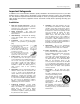
ENG Important Safeguards Important Safeguards In addition to the careful attention devoted to quality standards in the manufacture process of your video product, safety is a major factor in the design of every instrument. However, safety is your responsibility too. This sheet lists important information that will help to assure your enjoyment and proper use of the video product and accessory equipment. Please read them carefully before operating and using your video product. Installation 1.
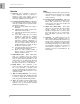
Important Safeguards Service Use 13. Servicing - Do not attempt to service this video equipment yourself as opening or removing covers may expose you to dangerous voltage or other hazards. Refer all servicing to qualified service personnel. 19. Cleaning - Unplug the video product from the wall outlet before cleaning. Do not use liquid cleaners or aerosol cleaners. Use a damp cloth for cleaning. 14.
ENG General Precautions General Precautions 1. All warnings and instructions of this manual should be followed 2. Remove the plug from the outlet before cleaning. Do not use liquid aerosol detergents. Use a water dampened cloth for cleaning 3. Do not use this unit in extremely humid or wet places (i.e. Restaurant Kitchen, inside a Sauna, etc.) 4. Keep enough space around the unit for ventilation. Slots and openings in the storage cabinet should not be blocked 5.
LW1010 / LW1012 Features LW1010 / LW1012 Features ‘EWT’ Eliminates Interference From Most Household Devices Fast & Easy Installation- Plug Into any AC Outlet Receiver Connects to any TV/VCR/DVD Recorder Indoor / Outdoor Night Vision Camera Built-in Microphone for Listening Ability Camera can be Battery Operated Up to 300ft Wireless Transmission Range* Night Vision Allows for Low Light Viewing up to 23ft (7m) from Camera** Receiver Automatically Switches View Between Cameras*** Deskto
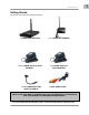
ENG Getting Started Getting Started The System comes with the following components: 1 x WIRELESS RECEIVER 1 / 2 x POWER ADAPTOR (FOR CAMERA) * 1 / 2 x CAMERA BATTERY ADAPTOR CABLE * 1 / 2 x WIRELESS CAMERA * 1 x POWER ADAPTOR (FOR RECEIVER) 1 x RCA VIDEO CABLE CHECK YOUR PACKAGE TO CONFIRM THAT YOU HAVE RECEIVED THE COMPLETE DVR, INCLUDING ALL COMPONENTS SHOWN ABOVE.
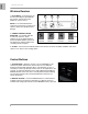
Wireless Receiver Wireless Receiver 1. DC 9V INPUT – Connection port for the 9V Power Adaptor (provided with this system). Connect the Power Adaptor to a power source. 1 2 3 NOTE: It is recommended that the receiver be connected to a surge bar or similar to protect the equipment from damage. 2. CAMERA CONNECTION DIP SWITCHES - Use the DIP Switches to search for cameras. These switches are set to default positions (based on Model Number).
ENG Wireless Receiver Installation Wireless Receiver Installation 1. Connect the AV Cable to the back of the receiver. Connect the other end of the Cable to the Video IN (Yellow) and Audio IN (White) ports on the TV, VCR or other viewing monitor. 2. Plug the Receiver power cable into the 9V POWER input. Plug the power cable into a wall outlet or surge protector. 3. Place the receiver in a place that will have clear reception to your camera(s).
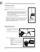
Camera Installation Installing the Camera: 1. Carefully unpack the Camera. 2. Decide whether the camera will be permanently wall mounted or sit on a tabletop: • • If you decide to place the camera on a tabletop or other flat surface, the camera can easily be moved to different locations as desired. It is strongly recommended that the camera be affixed to the table top surface to prevent damage to the camera in case of tabletop surface movement or improper handling.
ENG 4. Replace the camera in the desired mounting position. Tighten the side screw to secure the camera to the Stand. Adjust the angle of the camera until the desired view is set. Connecting Camera Power The Camera can be powered either by using the provided Power Adaptor, or using a 9v battery and the Battery Adaptor Cable: • • POWER ADAPTOR: Connect the Power Adaptor to the Camera. BATTERY: Connect the battery adaptor cable.
Troubleshooting Troubleshooting If you have problems with your System, there is often a quick and simple solution. Please try the following: Problem There is no picture from a Camera. There is Interference with the Camera Picture. Solution • Check all connections to the Camera. Make sure the adaptor is plugged in. • Make sure that the Cameras and Receiver are both ON. • Make sure that the receiver is set to search for the Camera (using the DIP Switch settings).
Appendix #1 - Receiver Specifications Feature Frequency Specification 902MHz ~ 928MHz Signal / Noise Ratio Operating Temperature Output 48dB -10°C ~ 40°C RCA Audio / Video Humidity Less than 85% Current Consumption Approx. 80mA Overall Size (W x L x H) 2.5” x 3.4” x 0.5” Appendix #2 - Camera Specifications Feature Specification TV System NTSC Resolution 360 Horizontal TV Lines High-Speed Electronic Shutter Image Sensor 1/60~1/15,000 1/3” CMOS Minimum Illumination 0.
It’s all on the web Product Information Specification Sheets User Manuals Software Upgrades Quick Start Guides Firmware Upgrades VISIT www.lorexcctv.com www.lorexcctv.com Lorex Technology Inc.