9 Channel Digital Video Recorder DXR109 FOR MORE INFORMATION WWW.STRATEGICVISTA.
Under the copyright laws, this documentation may not be copied, photocopied, reproduced, translated, or reduced to any electronic medium or machine-readable form, in whole or part without the prior written consent of Strategic Vista Technologies Inc., except in the manner described in the documentation. © Copyright 2003 Strategic Vista 300 Alden Road Markham, Ontario L3R 4C1 CANADA All rights reserved. Printed in Taiwan. THIS DEVICE COMPLIES WITH PART 15 OF THE FCC RULES.
Table of Contents Important Safety Instructions..........................................................................................................................................................................3 Introduction........................................................................................................................................................................................................4 Features ......................................................................
Important Safety Instructions All the safety and operating instructions should be read before operating this equipment. The improper operation may cause irreparable damage to the appliance. Lift and place this equipment gently. Do not expose this equipment to direct sunlight. Do not use this equipment near water or in contact with water. Do not spill liquid of any kind on the equipment. Do not unplug the power connector before turning the power off correctly.
Introduction The DXR109 combines a 9 channel multiplexer with a Digital Video Recorder (DVR). The DVR offers many advantages over traditional time lapse VCR’s, allowing you to quickly access and search for a specific time segment or event, which has been recorded. This high quality recorded video can be viewed at various playback speeds as well as frame-by-frame with the Jog Button feature To learn more about StrategicVista products, please visit our website at www.strategicvista.
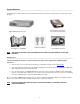
System Contents The DXR109 box should include the items listed below. Please take a moment to verify that no items are missing from the package. Hard Disk Drive in Cartridge (not included in all models) DXR109 Digital Video Recorder Installation / User NOTE: Manual 2 Keys for Hard Drive Cartridge Power Adapter and Cord KEEP THE KEYS IN A SAFE PLACE. THEY ARE NECESSARY FOR INSTALLATION / REMOVAL OF THE HARD DISK DRIVE.
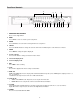
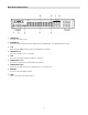
Front Panel Controls 18 17 16 15 LOREX 1 2 3 4 5 6 7 8 9 10 11 12 13 1. REMOVABLE HDD CARTRIDGE Please refer to Appendix #1. 2. MENU Press MENU to enter or exit the system setup menu. 3. ENTER Press ENTER to select an item for change while in the setup menu. 4. SELECT Press the SELECT button to change the camera shown i n the individual panes of the multi screen modes. 5. ZOOM Press ZOOM to enlarge the picture display 2x. 6.
15. PAUSE / Up Pause: Under DMR play mode, it can pause the action. UP: When in the setup mode, it works as an Up directional button. 16. LED INDICATORS These LED Light are ON under following condition. • HDD Full: HDD is full • ALARM: If you want to turn off the ALARM LED light, please refer to page 13 and set the Camera / ALARM item as OFF (all of the cameras should be set as OFF.) • TIMER: When Timer is set as Enabled • PLAY: On Play mode • REC: On Recording mode 17.
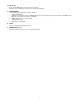
Back Panel Connections 1. POWER INPUT Connects to the Power cord. 2. EXTERNAL I/O Connects to a PC for Remote Control via RS-232 or to an Alarm Block. (see appendix 6 for more info) 3. 75/HI When using the LOOP function, allows for HI impedance or 75ohms. 4. VIDEO INPUT (1-9) Connects to a video source i.e. (camera). 5. CALL Connects to the CALL monitor for real time sequencing. 6. AUDIO OUTPUTS (1-2) Connects to a speaker (or a monitor with audio speaker). 7.
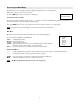
Accessing the Main Menu The Menu allows you to configure your DVR settings and program various recording options. Follow these steps in order to access the Menu: Press the MENU button. The password screen will appear: Password: 0000 The default Password is 0000. To change the number of the Password, use the ? / ? buttons to scroll left and right between numbers, and use the ? / ? buttons to change the value of the number that is flashing. Press the ENTER button once the correct Password is entered.
System Set Up The system menu is used to configure the system level o ptions of the DXR109… To access the System features, press MENU followed by the 4-digit password. Use the ? / ? to scroll to the ‘System’ option and press ENTER.
Setting the Motion Audible Alarm feature If enabled, the buzzer will sound if the video motion detect feature is set and motion is detected. 5. 6. 7. 8. On the System screen, press ? / ? to select Motion Audible Alarm, then press ENTER. Press ? / ? to enable or disable the External Audible Alarm Device. Options are: ON = Buzzer will sound when motion is detected. OFF = The buzzer will remain silent when motion is detected. Press MENU to confirm your change.
1. 2. 3. 4. On the System screen, press ? / ? to select System Time & Date, then press ENTER. Press ? / ? to choose a number, then press ? / ? to move to the next digit: 2003-Jan-01 (Mon) 22:38:29 Press MENU to confirm your change. Press ? / ? to move to another field on the System screen or press MENU to exit this screen and confirm the current operation. Changing the System Password 1. 2. 3. 4. 5. On the System screen, press ? / ? to select New Password, then press ENTER.
Remote Protocol Setup This feature is used to set the basic RS-232/RS-485 protocols to control the DVR remotely from a PC. Pressing ENTER after scrolling to the Remote option will bring up the following menu options: Remote mode: Selects whether to use an RS-232 or RS-485 interface. Baud rate: Selects the baud rate (bps) to be used for the connection. The available settings are: 115200, 57600, 19200, 9600, 3600, 2400, 1200.
2. Use the ? / ? scroll keys to move to START record time 00:00 (HH:MM) Press ? / ? to set the start time 3. Press ? / ? move to END record time 00:00 (HH:MM) Press ? / ? to change END record Time numerical digit 4. Press ? / ? move to QUALITY Press? / ? to choose options of BEST, HIGH, NORMAL, BASIC 5. Press ? / ? move to Record IPS (Images Per Second) Press? / ? to choose one of the following options NTSC: 15A, 15, 8, 4, 2, 1 PAL: 12A, 12, 6, 3, 2, 1 6.
Record Settings On the Main menu, selecting the Record option will allow you to set the quality and speed of recordings. Pressing ENTER after scrolling to the Record option will bring up the following menu options: (RECORD) HDD Overwrite: NO Record IPS: 25A Record Quality: Normal Alarm Rec IPS: 25A Alarm Rec Quality: Normal Motion Trigger Record: ON HDD Overwrite Setup: 1. Press ENTER to confirm HDD OVERWRITE setup. 2. Press ? / ? to choose HDD OVERWRITE.
Camera Channel Setup To access the Camera option, press MENU followed by the 4-digit password. Use the ? / ? to scroll to the Camera option and press ENTER. TITLE DWELL ALARM RECORD ---01 ON 5 5 5 LOW EVENT ---02 ON 5 ---03 ON 5 5 5 LOW EVENT 5 5 LOW EVENT ---04 ON 5 5 5 LOW EVENT The options available in this section are as follows… Title This feature is used to assign a 6 -character title to each camera input. 1.
Motion Detection The Motion Detect feature provides a visual indication on the monitor when movement is detected in the picture. Also, if the ‘Motion Trigger Record’ option is enabled in the ‘Record’ menu, recording will active on all cameras when motion is detected. Use the steps below to enable/disable the detection zones for each camera. Press MENU to enter the menu set up, then ? to CAMERA setup. Press ENTER twice to enter the Motion Detection Setup.
Figure 1-1 MOTION DETECTION SETUP – 1~9 1 2 3 4 5 6 7 8 9 10 11 12 13 14 15 032 -- -- -- -- -- -- -- -- -- -- -- -- -- -- -- Figure 1-2 MOTION DETECTION SETUP – LINE 1 2 3 4 5 6 7 8 9 10 11 12 13 14 15 032 -- -- -- -- -- -- -- -- -- -- -- -- -- -- -- Figure 1-3 MOTION DETECTION SETUP – ALL 1 2 3 4 5 6 7 8 9 10 11 12 13 14 15 032 -- -- -- -- -- -- -- -- -- -- 18 -- -- -- -- --
Event Log Viewing To access the Event Log Viewing option, press MENU followed by the 4-digit password. Use the ? / ? to scroll to the Event option and press ENTER to view the list of logged events. Use the ? / ? to scroll through the events on the display and ? / ? to go to the next page. To view the video associated with an event, scroll to the event and press ENTER. The following is a list of events that can be displayed on the DXR109.
Operation On Screen Display (OSD) The DXR109 will display all current status on the OSD. 2002 – JAN –01 01:02:03 Here is an example of the display. E 32GB The following status will be shown: Time and Date – The current time and date will be shown on the first line.
Picture in Picture (PIP): This button is used to configure the monitor so a full screen is displayed in the background with a 1/16th size screen insert. 1. 2. 3. Press the button to display the PIP mode. Press SELECT then ? / ? button to move the insert screen. Press MENU to exit Zoom: Feature is used to enlarge the display (2X) the size of the main picture.
Slow reverse Press PLAY on the front panel, then press SLOW for slow forward. Press REW/? to play images slowly forward (1/2X). Press REW/? again to slow the speed to 1/4X. Continue to press REW/? to slow down the speed. The minimum slow forward speed is 1/32X. Image Jog Press PLAY on the front panel, then press PAUSE to lock the current image on the screen. Press FF/? to select single image play. Each time you press FF/? the next image will display.
Troubleshooting PROBLEM SOLUTION HDD not found Need to insert HDD Make sure that the HDD Cartridge is locked, then press any key to continue No Power Check the power source cord connections Check that there is power at the outlet Buttons aren’t working when pressed Check if the system is in Key Lock mode Press MENU and ENTER at the same time to escape the Key Lock mode No recorded video Check that the HDD has been installed correctly Check that Timer / Alarm Enable is set to YES Check camera’s vid
Technical Specifications Video format NTSC/EIA or PAL/CCIR HDD storage IDE type, UTMA 66 above, 1 removable HDD supported Record mode Manual / Alarm / Timer Camera input signal Composite video signal 1 Vp -p 75O BNC, 9 Channels Camera loop back Composite video signal 1 Vp -p 75O BNC, 9 Channels Main monitor output Composite video signal 1 Vp -p 75O BNC Call monitor output Composite video signal 1 Vp-p 75O BNC Audio input/ output 4 audio inputs, (RCA) and 2 audio outputs, (RCA) Motion detect
Appendix 1: Installing the HDD NOTE: The HDD has the same purpose in a DXR109 as a videocassette does in a VCR. However, installing the HDD is a bit more complicated. Please follow the next steps carefully in order to ensure proper installation. The compartment (with the handle) located on the front panel of the DXR109 is the removable Cartridge Casing where the HDD is inserted. The various parts of the Cartridge Casing are labeled for your reference. Cartridge Casing 1. 2. 3.
Step 6: Secure the HDD in the cartridge casing. Position the HDD into place and secure it using the six screws supplied. Step 7: Slide the top Cover over the Cartridge Casing Slide the Cover forward over the Cartridge Case. Ensure it is secured in place over the release latch. Reinsert the Cartridge Casing into the DXR109 Step 8: Lock the Cartridge To Lock the cabinet, turn the key clockwise to Position A. A (locked) B (unlocked) To unlock the cabinet, turn the key counter-clockwise to Position B.
Appendix 2: Connection Diagram to Cameras and Monitor Video Camera 9 .. . . 2 Main Monitor 1 ....
Appendix 3: Pin Configurations 9 pin Com Port 25 Pin Com Port 28
Pin References for RS-232 / Alarm Block PIN 1. GND GROUND PIN 18. ALARM INPUT 1 Used to connect an alarm sensor between ALARM INPUT 1 (PIN 18) and GND (PIN 1) to trigger an alarm on Camera 1, which can activate the internal audible alarm and start recording. PIN 5. ALARM INPUT 2 Used to connect an alarm sensor between ALARM INPUT 2 (PIN 5) and GND (PIN 1) to trigger an alarm on Camera 2 which can activate the internal audible alarm and start recording. PIN 17.
Appendix 4: Rack Mount Installation Screws and brackets for rack mounting applications can be purchased as an optional accessory. Front Angle with Rack Mount Side View with Rack Mount For more information about the rack mount & other accessories through Strategic Vista, please visit: www.strategicvista.
Appendix 5: Recording Times (in Hours) NTSC SYSTEM IPS 25A 15 8 4 2 1 Best 16hr 32hr 60hr 120hr 240hr 480hr High 20hr 40hr 75hr 150hr 300hr 600hr Normal 32hr 64hr 120hr 240hr 480hr 960hr Basic 54hr 105hr 200hr 400hr 800hr 1600hr Record Quality HDD Type 80GB IPS 25A 15 8 4 2 1 Best 24hr 48hr 90hr 180hr 360hr 720hr High 30hr 60hr 1136hr 225hr 450hr 900hr Normal 48hr 96hr 1600hr 360hr 720hr 1440hr Basic 80hr 160hr 300hr 600hr 1200hr 2400hr
Appendix 6: RS232 Remote Protocol The RS-232 protocol allows you to control the DXR109 from a PC or any other serial device.
Appendix 7: Compatible HDD Brands Manufacturer Capacity Rotation Deskstar 180 GXP (120 GB) Deskstar 7K250, HDS722516VLAT20 Deskstar 7K250, HDS722525VLAT80 120GB 160GB 250GB 7200 rpm 7200rpm 7200rpm Deskstar 120GXP (80GB) Deskstar 120GXP (120GB) 80GB 120GB 7200 rpm 7200 rpm Maxtor DiamondMax 536DX(60GB) 4W060H4 60GB 5400rpm Maxtor Maxtor DiamondMax Plus 9 DiamondMax Plus 9, Model#6Y120L 80GB 120GB 7200 rpm 7200 rpm Maxtor Seagate Seagate DiamondMax Plus 9, Model#6Y160L0 Barracuda ATA IV, S
Limited Warranty LOREX PRODUCT LIMITED WARRANTY LOREX warrants, to the original reta il purchaser only (the “Purchaser”), that this item (the “Product”) is free from manufacturing defects in material and workmanship, provided the Product is used in normal conditions and is installed and used in strict accordance with the instructions conta ined in the Product’s Owner’s Manual.
Care & Maintenance Please follow these instructions to ensure proper care and maintenance of this system Keep your monitor and camera dry. If it gets wet, wipe it dry immediately. Use and store your unit in normal temperature environment. Extreme temperatures can shorten the life of the electronic devices. Handle the monitor carefully. Dropping it can cause serious damage to the unit. Occasionally clean the unit with a damp cloth to keep it looking new.