4 CHANNEL NETWORKABLE DIGITAL VIDEO RECORDER Instruction Manual English Version 1.0 MODEL: L3104 www.lorexcctv.com Copyright (c) 2006 LOREX Technology Inc.
Thank you for purchasing the 4 Channel Network Digital Video Recorder. Lorex is committed to providing our customers with a high quality, reliable security product. The LOREX L3104 Network DVR records in Real Time on 4 Channels with 120 fps recording capability. Images can be easily transferred using the USB flash drive. The system can be viewed and controlled over the internet from a remote location with trouble free access via the Free DDNS Service.
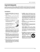
Important Safeguards Important Safeguards In addition to the careful attention devoted to quality standards in the manufacture process of your video product, safety is a major factor in the design of every instrument. However, safety is your responsibility too. This sheet lists important information that will help to assure your enjoyment and proper use of the video product and accessory equipment. Please read them carefully before operating and using your video product. Installation 1.
Important Safeguards Service Use 13. Servicing - Do not attempt to service this video equipment yourself as opening or removing covers may expose you to dangerous voltage or other hazards. Refer all servicing to qualified service personnel. 19. Cleaning - Unplug the video product from the wall outlet before cleaning. Do not use liquid cleaners or aerosol cleaners. Use a damp cloth for cleaning. 14.
General Precautions NOTE This equipment has been certified and found to comply with the limits regulated by FCC, EMC, and LVD. Therefore, it is designated to provide reasonable protection against interference and will not cause interference with other appliance usage.
Observation System Features DVR System Features • High quality recording with modified MJPEG compression (5~20Kbyte/frame) • USB port for transferring critical images and firmware upgrade • 120 fps recording speed for Real Time display & recording on 4 channels • Programmable Video Motion Detection • 4 camera inputs (4 BNC) • Pre-alarm recording feature • High quality recording with modified MJPEG compression (5~20Kbyte/frame) • Audio Recording Function is available • Internet / Web Ready – view and contro
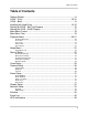
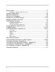
Table of Contents Table of Contents Getting Started .......................................................................................... 9 L3104 - Front ..................................................................................... 10-12 L3104 - Back ........................................................................................... 13 Installing the Hard Drive ..................................................................... 14-15 Starting the DVR - Self Test Screens .............
Backup Menu .......................................................................................... 37 Backup Menu - Backup to USB Memory Stick .......................................................................... 37 Password Setup Menu ............................................................................ 38 Network Connectivity .............................................................................. 39 Router Port Forwarding ............................................................
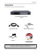
Getting Started Getting Started The L3104161 system comes with the following components: 4 Channel Network Digital Video Recorder Standard Power Cable 4 x Cables Removable HDD Drive Keys HDD Reader / Remote Manager Software CHECK YOUR PACKAGE TO CONFIRM THAT YOU HAVE RECEIVED THE COMPLETE SYSTEM, INCLUDING ALL COMPONENTS SHOWN ABOVE.
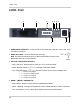
L3104 - Front L3104 - Front 1 2 3 4 5 6 7 8 9 10 1. REMOVABLE DRIVE BAY - Install location for the removable hard drive. See Page 14 for installation instructions. 2. DRIVE BAY LOCK - Locks the Removable Drive Bay. Note: The DVR unit will not power on or detect the Hard Drive correctly if the Removable Drive Bay is not locked first. 3. CH1-CH4 / DIRECTION CONTROLS • Main: CH1-CH4 - Switch between Channels 1-4 in Full Screen Mode.. • Menu: Direction Controls (Ø×ÕÖ) - Navigates within Menu Mode.
L3104 - Front L3104 - Front 1 2 3 4 5 6 7 8 9 10 5. ALARM / + (PLUS) / CH • Main: Alarm- Turns off the Alarm Buzzer (when an Alarm Event is active). • Menu: + (Plus) - Changes selected options in Menu Mode (Numbers, Letters and Values). • Play: CH - Switches between Channels in playback mode. 6. REC / ENTER • Main: REC - Starts and Stops the active recording. • Menu: Enter - Accesses Menu options (move forward through menu options).
L3104 - Front L3104 - Front 1 2 8 3 4 5 6 7 9 10 11 8. HDD ACCESS LED - The LED indicator will flash when the Hard Drive is accessed, or when events are being recorded. 9. USB PORT - Access port for backup to a USB Memory Stick or upgrading the DVR FIrmware 10. JOG / SHUTTLE CONTROL - Controls the playback of previously recorded events: • Jog Control (Inner Circle Control) - Search through playback one frame at a time.
L3104 - Back L3104 - Back 1 2 3 7 8 4 5 6 9 1. VIDEO IN BNC PORTS - Channel 1-4 camera inputs (used to connect Cameras with BNC connection type). 2. VIDEO OUT BNC PORT - Connect the RCA output to display the DVR's Menu and Video Playback. 3. AUDIO IN RCA PORT - Use with A/V cables to receive audio from an external source. 4. ETHERNET PORT - Connects the DVR to a router for connection to the internet. Refer to the instructions on Page 39 for Remote Connection details. 5.
Installing the Hard Drive Installing the Hard Drive The Hard Drive serves the same purpose in a DVR as a video cassette does in a VCR. Please follow the steps carefully in order to ensure proper installation. The compartment located on the front panel of the DVR is the removable Cartridge Casing in which you insert the Hard Drive. The various parts of the Cartridge Casing are labeled for your reference. STEP 1: Remove the Cartridge Casing from the DVR. • Lift the Handle and pull towards you.
Installing the Hard Drive STEP 4: Secure the Hard Drive in the Casing • Use screws and tighten them, positioning the Hard Drive into place. This step is optional, but it is recommended. Position Hard Drive and secure with provided screws STEP 5: Slide the top Cover over the Cartridge Casing • Slide the Cover forward over the Cartridge Case. Ensure it is secured in place over the release latch.
Starting the DVR - Self Test Screens Starting the DVR - Self Test Screens Once the DVR has been connected and powered on, the following self-test screens will appear: CHECK HARD DISK ... OK! COLOR TEST SCREEN HDD TEST SCREEN NOTE: If a new HARD DRIVE is detected by the system, the DVR will display “FORMAT HARD DRIVE Y/N?”. Choose YES to format the drive. Data will not be written to the Hard Drive if it has not been formatted. SYS INFORMATION BOARD VER: REV. #.
Starting the DVR - QUAD Display Starting the DVR - QUAD Display After the system self-tests have been completed, the DVR will switch to the CAMERA viewing screens (in QUAD MODE) with the following information displayed on screen: • CH1-CH4: Camera title indicators • MM/DD/YYYY - HH:MM:SS: The current system date and time. If a camera is not detected, the associated portion of the QUAD display will display a BLUE SCREEN.
Main Menu Control Main Menu Control • Enter the MENU screen by pressing the MENU button. • Scroll through the 4 Main options by pressing the UP and DOWN buttons. Use the + and buttons to change the options within a setting. • To enter a sub-menu, navigate to the option and press the ENTER button. • To exit a SUBMENU, press the ESC button. A prompt appears to SAVE CHANGES - press ENTER to save the changes or press ESC to exit without saving.
Main Menu Tree Main Menu Tree Main Menu Playback Go To First Go To Last Time & Date Event Search Setup Record Setup Voice Setup Camera Setup Alarm Setup Display Setup Network Setup Initialize Event Log HDD Information Backup Password Setup Password User Name New Password 19
Playback Menu Playback Menu This submenu allows you to locate and playback previously recorded events.
Playback Menu Playback Menu Go To First Begins playback at the first recorded event. Go To Last Begins playback (in reverse) at the last recorded event. Time & Date Search for previously events by date and time. recorded Time & Date Play Date: Play Time: Play Start First Record: First Time: Last Record: Last Time: MM-DD-YY HH:MM:SS MM-DD-YY HH:MM:SS MM-DD-YY HH:MM:SS 1. PLAY DATE: Locate the date for a previously recorded event. To change the setting, press the ENTER button to highlight.
Playback Menu Event Search Search and Replay previously recorded events Event Search Log View Log View Log Search Log Search Alarm Log Motion Log VLoss Log Schedule Log Normal Recording Log View 1. LOG VIEW: Lists previously recorded events by Date, Time and Channel Number as: MM-DD-YYYY HH:MM:SS CH# RECORD Navigate using the K and L buttons, and press ENTER to start viewing the selected event. Press ESC to exit view mode. 2.
Setup Menu Setup Menu This submenu allows you to change the SETTING options for the DVR unit. Selecting options on this Menu will access additional settings and options.
Setup Menu Camera Setup Camera Titles Camera 1: CAM1 Camera 2: CAM2 Camera 3: CAM3 Camera 4: CAM4 Brightness CAM1 CAM2 CAM3 CAM4 0 Contrast Display Setup 24 0 Alarm ON/OFF CH1 Alarm: OFF CH2 Alarm: OFF CH3 Alarm: OFF CH4 Alarm: OFF Alarm Attribute CH1 Alarm: NO CH2 Alarm: NO CH3 Alarm: NO CH4 Alarm: NO Video Loss Alarm CH1 Alarm: OFF CH2 Alarm: OFF CH3 Alarm: OFF CH4 Alarm: OFF Alarm Hold: 5 Sec Buzzer Out: OFF TIme Display: ON Title Display: ON Voice Display: ON HDD Capacity: ON Border Col
Setup Menu Network Setup IP Setup IP: 192.168.000.111 Subnet Mask: 255.255.255.0 Gateway: 192.168.000.
Record Setup Record Setup Changing Quality settings will generate different file sizes - a lower quality setting will result in a smaller the image, however the quality of the images will be reduced. See Page 55 for the Recording Details Chart. Alarm Record Setup Alarm Record Setup CH1 Alarm Record Setup CH2 Alarm Record Setup CH3 Alarm Record Setup CH4 Alarm Record Setup Pre Alarm: OFF Post Alarm: OFF Alarm Record: OFF Color: Color Record Quality: High IDSM Sensitivity: High Record Speed: 30 FPS 1.
Record Setup 1. CH1 - CH4 MOTION RECORD SETUP: Setup for Motion Detection on individual cameras. Press the K and L buttons to highlight, and press the ENTER button to access the individual settings for each camera: • Motion Sensitivity: Sets the Motion Sensitivity ON/OFF.
Record Setup • SET SCHEDULE: Configures the schedule for individual Cameras. Press the K and L buttons to highlight the Set Schedule option and press ENTER. Press ENTER again to add or modify the schedule(s): Schedule Record: OFF Color: Color Record Quality: High IDSM Sensitivity: Standard Record Speed: 30 FPS SET SCHEDULE SET RECORD Schedule is Empty Line 01 Add Modify Remove z ADD: Add a new scheduled recording time. Select the ADD option and press ENTER.
Voice Setup Overwrite Setup Allows the DVR to overwrite previously recorded data, or to stop the recording once the hard drive is full. Overwrite Setup Overwrite: ON Warning Signal: OFF Warning Duration: 10 Sec 1. OVERWRITE: Allows the Hard Drive data to be overwritten once the drive becomes full. Press the K and L buttons to highlight, and press the ENTER button to set to ON or OFF. NOTE: If Overwrite is set to OFF, recording will stop once the drive is full. 2.
Camera Setup Camera Setup Camera Titles Camera Titles Camera 1: CAM1 Camera 2: CAM2 Camera 3: CAM3 Camera 4: CAM4 Configure the Title for individual cameras (8 character maximum). Press the K and L buttons to select a camera, and press the ENTER to enter edit mode. Use the + and - buttons to set the Title (A-Z, and 0-9) to a maximum of 8 characters. Press the ESC key to exit the submenu Press ENTER to accept the change, or ESC to cancel all changes.
Alarm Setup Alarm Setup Alarm ON/OFF Alarm ON/OFF Turns Alarm Detection ON/OFF for each channel on the alarm block. Press the K and L buttons to select a channel, and press the + and - keys to change the setting to ON or OFF. CH1 Alarm: OFF CH2 Alarm: OFF CH3 Alarm: OFF CH4 Alarm: OFF Alarm Attributes Alarm Attribute Sets Alarm Attribute type for each channel on the alarm block.
Display Setup Display Setup 1. TIME DISPLAY: Turns the onscreen Time display ON or OFF. Navigate using the K and L buttons, and press + and - to change the setting to ON or OFF. 2. TITLE DISPLAY: Turns the onscreen Camera Title display ON or OFF. Navigate using the K and L buttons, and press + and - to change the setting to ON or OFF. 3. VOICE DISPLAY: Displays an indicator icon on the channel currently sending sound. Navigate using the K and L buttons, and press + and - to change the setting to ON or OFF.
Network Setup Network Setup IP Setup IP Setup 1. IP: Configure the IP address for the DVR unit. Navigate using the K and L buttons. Press the < and > buttons to move within the IP address, and press + and - to change the numbers. IP: 192.168.000.111 Subnet Mask: 255.255.255.0 Gateway: 192.168.000.001 TCP Port: 2505 HTTP Port: 0050 DHCP: Disable MAC: 01:23:45:67:89:AB 2. SUBNET MASK: Configure the Subnet Mask for the DVR unit. Navigate using the K and L buttons.
Network Setup DDNS Setup DDNS Setup 1. DDNS: Sets using DDNS to YES or NO. Navigate using the K and L buttons. Press the < and > buttons to move within the IP address, and press + and - to change the letters and numbers. DDNS: NO Domain: Username: Password: Use Public IP: YES DDNS Status: APPLY 2. DOMAIN: Enter the Domain (web address) that the DVR will connect to for remote viewing. Navigate using the K and L buttons.
Initialize Initialize 1. HDD FORMAT: Formats the Hard Drive (deletes all recorded data). Navigate using the K and L buttons, and press ENTER to Format. A prompt will appear to confirm the format - Press ENTER again to accept the Formatting, or press ESC to exit. 2. FACTORY SETTINGS: Resets the DVR to Factory Defaults. Navigate using the K and L buttons, and press ENTER. A prompt will appear to confirm the reset - Press ENTER again to accept the Reset, or press ESC to exit.
Event Log Event Log The Event Log section records DVR System Events, and provides the capability to search and playback previously recorded events. See Pages # - # for further details. Log View Event Log System Log Log Search Alarm Log Motion Log VLoss Log Schedule Log Normal Record Log HDD Information Displays Hard Drive information. This information is View Only, and cannot be changed with the DVR. HDD Information Model: Serial: Usage: #.
Backup Menu Backup Menu A USB Memory Stick can be connected to the front panel of the DVR, and is used as a backup device. Connect the Memory Stick to the DVR, and select the Backup Menu option from the Main Menu. One of the following prompts will appear: • NO Memory Detected: Indicates that the Memory Stick is not recognized by the DVR. • Initializing Memory - Indicates that the Memory Stick is recognized, however the Format of the drive is not correct. The following message appears: Unknown Data Exists.
Password Setup Menu Password Setup Menu Controls the User and Password Setup for the DVR. The Password is a combination of numbers 1-4 (default password is 11111111) Password Setup Password: OFF User Name: Admin New Password 1. PASSWORD: Turns the use of Passwords ON or OFF. Navigate using the K and L buttons. Press the + and - to change the setting to ON or OFF. 2. USER NAME: Setup for individual system users. Navigate using the K and L buttons.
Network Connectivity Network Connectivity The DVR unit can be controlled using your existing network and a PC. Control of the unit can occur from within your local network, or remotely over the Internet. 1. Enable PORT FORWARDING on your Router. Refer to the instructions on Page 40 for details. DVR 2. Set up a web account at http:// DDNS.strategicvista.net. Refer to Pages 41-42 for setup and configuration instructions. 3. Connect the DVR to the Router Power the Observation unit on.
Router Port Forwarding Router Port Forwarding You will need to enable port forwarding on your Router to allow for external communications with your DVR. The following ports will need to be forwarded to remotely connect to your DVR: • DVR PORT: 2505 (or any other port you selected to use during setup) • WEBSERVER PORT: 80 (or any other port you selected to use during setup) Computers, DVRs, and other devices inside your network can only communicate directly with each other within the internal network.
Setting Up Your DDNS Account Setting Up Your DDNS Account Lorex offers a free DDNS server for use with your System. A DDNS account allows you to set up a web site address that points back to your Local Network. The following outlines how to set up your free DNS account. 1. Navigate to http://DDNS.strategicvista.net 2. Select the Create Account option from the list on the left side of the screen. 3.
Setting Up Your DDNS Account 4. Complete the System Information fields as follows: • Product License: Select your product model from the Product License drop down menu • - : Locate the MAC address of your (recorded while loading the System) • URL Request: Choose a URL for your DDNS connection (i.e. your name, your company or business name, or anything of your choice.) NOTE: The URL request must not exceed 8 CHARACTERS 5.
Setting up DDNS on the DVR Setting up DDNS on the DVR Once the DDNS Account has been configured (and the account details received in Email), then these settings can be added to the DVR unit. 1. Press the Menu button on the front panel of the DVR. Select the Network Set option. • Set DDNS to YES • Setup the Domain Name, User Name and Password manually, based on the settings received in email.
DVR Manager Software DVR Manager Software Minimum System Requirements: • Operating System: Windows XP • CPU: Pentium 4 1.7GHZ or greater • Memory: 128 MB or greater • Hard Drive Space: Varies depending on the amount of data to be saved Installing the Software Run the DVR Manager 3 Software SETUP from the provided CD: 1. Click on NEXT to begin the setup process 2. Select the INSTALL directory (or leave the default install location).
DVR Manager Software 3. The Installation Progress window will appear. Click the ABORT button ONLY if you wish to stop the installation process. 4. Once the DVR Manager application has been installed, click the OK button to continue.
DVR Manager Software Using the DVR Manager Application Launching the DVR Manager application will open the Manager window: 1 2 3 4 5 9 8 7 6 1. CONNECTION INDICATOR: Indicates the connection status to the DVR. The displayed IP address is for the DVR. 2. CONFIGURATION BUTTONS: Configuration and use options for the DVR Manager Software: • CONFIG BUTTON: Connection Configuration for the DVR.
DVR Manager Software • CONN BUTTON: Connects to the DVR using the settings as specified on the CONFIG Button. • INFO BUTTON: Upgrades the DVR using the Network Connection, and provides contact information. NOTE: DVR Upgrades are periodically available on the LOREVCCTV.com website. It is recommended that you do NOT upgrade the DVR unless instructed by a technician or service professional. www.lorexcctv.com support@lorexcorp.
DVR Manager Software 5. SYSTEM STATUS INDICATORS: Shows the status of the current system • LIVE: Indicates Live Viewing mode • RECORD: Indicates the Recording status of the DVR. • REPLAY: Indicates that the current video is previously recorded. • TIME: Displays the current date and time of the DVR. 6. PLAYBACK CONTROLS: Controls the playback of previously recorded Video. • REW: Reverses playback speed (2X, 4X, 8X up to 8,192X). • PREV: Frame-by-Frame Playback of the previous image.
DVR Manager Software 8. CHANNEL SELECTION BUTTONS: Selects the View Mode for the DVR Manager Software: • SEQ: Displays current video in SEQUENCE MODE. • QUAD: Displays current video in QUAD MODE. • CH 1-4: Displays an individual CHANNEL in FULLSCREEN MODE. 9. REC / ESC BUTTON: Turns on RECORDING / stops RECORDING.
Using the Memory Stick with a PC Using the Memory Stick with a PC Once data has been copied from the DVR to the the USB Memory Stick, data can be replayed on the PC. 1. Connect the Memory Stick to the PC USB Port. Once the drive is detected, run the READER.exe file located on the Memory Stick drive to extract the Reader software to the Memory Stick. 2. Locate the file DVR_Reader.exe to run the Viewer Software NOTE: The Backup Video can only be played using this application.
Troubleshooting Troubleshooting When a malfunction occurs, it may not be serious and can be corrected easily. The following describes the most common problems and solutions.
Troubleshooting Problem: The image on the DVR does appears, but does not have sound Check: • Check the VOLUME • Check the CAMERA connection to the DVR • Confirm that the Camera has sound capabilities (Refer to the manual for the camera model for further information on the Camera functionality) Problem: The picture on the DVR is poor, shrinks or flickers Check: • Check the camera video cable and connections • Disconnect and reconnect the cable at the DVR and at the Camera • Clean the camera lens • Adjust t
DVR Specifications - Appendix #1 DVR Specifications - Appendix #1 Video Signal Video Signal System NTSC/PAL (Auto Detection) Video Inputs 4 Channels Video Input Signal NTSC/PAL Composite, 75OHM, 1.0vpp Video Out 1 Video Monitor, 1 S-VIDEO Video Output Signal NTSC/PAL Composite, SVHS Audio Input 1 Channel Audio Input Signal RCA Audio Output 1 Channel Audio Output Signal RCA Display Features Display Format 120 (NTSC) / 100 (PAL) FPS Sequencing (Dwell) Yes (Interval time 1~10 sec.
DVR Specifications - Cont. DVR Specifications - Cont. Connectors Video Inputs 1 BNC Video Output 1 BNC, 1 SVHS Alarm In/Out Terminal Block Ethernet RJ45 Alarm Alarm Inputs 4 Inputs Alarm Output 1 Output Multiple Alarm Display Yes Alarm Duration Available Video Loss Duration Yes Environmental Operating Temperature 41°F ~ 104°F 5°C ~ 40°C Humidity 20% ~ 80% As our products are subject to continuous improvement, LOREX Technology Inc.
DVR Specifications - Cont. Recording Details - Appendix #2 Display & Recording Display Resolution 720x480 (NTSC) 720x576 (PAL) Display Format 1 Channel or QUAD Channel Recording Mode 1 Channel at 360x240 Pixels Record Quality 4 Levels.
DVR Specifications - Cont. QUALITY: STANDARD IDSM: LOW 15 KB/Frame HDD Capacity (GB) 1 fps (hrs) 4 fps (hrs) 8 fps (hrs) 16 fps (hrs) 30 fps (hrs) 40 718.5 179.6 89.8 44.9 24.0 60 1077.8 269.4 134.7 67.4 35.9 80 1437.0 359.3 179.6 89.8 47.9 120 2155.6 538.9 269.4 134.7 71.9 160 2874.1 718.5 359.3 179.6 95.8 200 3592.6 898.1 449.1 224.5 119.8 300 5388.9 1347.2 673.6 336.8 179.6 400 7185.2 1796.3 898.1 449.1 239.
Connecting Cameras - Appendix #3 Connecting Cameras - Appendix #3 The L3104161 DVR includes 4 x 1/4” Color CCD DIN Cameras. Additional cameras can be added to the 4 additional camera inputs using the DIN or BNC ports. BNC Connected Cameras BNC connected cameras are not included with the DVR, however can be ordered online at www.lorexcctv.com DVR BNC Cameras have several cables and receive power from a wall outlet 1.
Connecting to an Observation System - Appendix #4 Connecting to an Observation System - Appendix #4 The DVR can be used with an Observation System (not included). NOTE: The CH1 - CH8 BNC Video inputs serve as Looping Video Outputs by individual channels when a DIN camera is connected to the associated channel on an Observation System. OBSERVATION SYSTEM (Not Included) 1. Attach the BNC to RCA (Male to Female) adapters on the BNC CH1-CH8 found on the DVR. 2.
Connecting a TV/Slave Monitor - Appendix #5 Connecting a TV/Slave Monitor - Appendix #5 Connections to a TV or Slave Monitor (not included) can be made in several different ways on the back of the DVR. Connecting to a TV DVR 1. Connect the SLAVE VIDEO OUT port on the back of the DVR to the VIDEO IN port on the back of the TV. 2. Connect the SLAVE AUDIO OUT port on the back of the DVR to the AUDIO IN port on the back of the TV. Connecting to a TV or Monitor with S-Video 1.
Full Connectivity Diagram - Appendix #6 Full Connectivity Diagram - Appendix #6 The following diagram outlines a general set of connections available with the L400 Series DVR.
Optional Accessories Optional Accessories The following accessories are available to add to your existing system CABLE OBSERVATION SYSTEM / MONITOR Extends the length between the CAMERA and MONITOR.
It’s all on the web Product Information Specification Sheets User Manuals Software Upgrades Quick Start Guides Firmware Upgrades VISIT www.lorexcctv.com wwwlorexcctv.com Strategic Vista International Inc.