DIGITAL VIDEO SURVEILLANCE RECORDER WITH MOTION DETECTION AND AUDIO RECORDING Instruction Manual English Version 1.0 MODELS: L204 & L208 Series www.lorexcctv.com Includes L204 & L208 Copyright © 2007 Lorex Technology Inc.
Thank you for purchasing the L200 Series Surveillance DVR. Lorex is committed to providing our customers with a high quality, reliable security product. The L200 series of Surveillance Digital Video Recorders provides professional grade features in a value package.
ENG Important Safeguards Important Safeguards In addition to the careful attention devoted to quality standards in the manufacture process of your video product, safety is a major factor in the design of every instrument. However, safety is your responsibility too. This sheet lists important information that will help to assure your enjoyment and proper use of the video product and accessory equipment. Please read them carefully before operating and using your video product. Installation 1.
Important Safeguards Service Use 13. Servicing - Do not attempt to service this video equipment yourself as opening or removing covers may expose you to dangerous voltage or other hazards. Refer all servicing to qualified service personnel. 19. Cleaning - Unplug the video product from the wall outlet before cleaning. Do not use liquid cleaners or aerosol cleaners. Use a damp cloth for cleaning. 14.
ENG General Precautions General Precautions 1. All warnings and instructions of this manual should be followed 2. Remove the plug from the outlet before cleaning. Do not use liquid aerosol detergents. Use a water dampened cloth for cleaning 3. Do not use this unit in humid or wet places 4. Keep enough space around the unit for ventilation. Slots and openings in the storage cabinet should not be blocked 5.
L200 Series Features L200 Series Features • • • • • • • • • • • • 4 or 8 Channel Triplex DVR (Simultaneously View, Record and Playback) Network ready (LAN support with remote client application) Efficient file transfer (MPEG4 network transmission) Excellent original image recording (MJPEG recording to disk) Connects to any monitor (VGA and composite monitor support) Easy file backup (Supports optional internal optical drive, USB, remote client recording) Large storage capacity (Supports 2 internal “securi
ENG Table of Contents Table of Contents Important Safeguards.................................................................................................................................... 3 General Precautions ..................................................................................................................................... 5 L200 Series Features....................................................................................................................................
Getting Started Removing the Back Cover and Installed Drive........................................................................................ 63 Setting the New Drive to Master.............................................................................................................. 63 Hard Drive Replacement (cont …).............................................................................................................. 64 Installing the New Drive..............................................
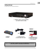
ENG Getting Started Getting Started The DVR comes with the following components: 1 x COMPACT DIGITAL VIDEO RECORDER (8 CHANNEL MODEL SHOWN) 1 x REMOTE CONTROL 1 x POWER ADAPTOR 1 x POWER ADAPTOR CABLE 1 x HARDWARE MANUAL 1 x QUICK START GUIDE 1 x SOFTWARE CD CHECK YOUR PACKAGE TO CONFIRM THAT YOU HAVE RECEIVED THE COMPLETE DVR, INCLUDING ALL COMPONENTS SHOWN ABOVE.
L200 Series - Front L200 Series - Front 1 2 3 7 1 2 3 CD/DVD-ROM Channel Buttons LED Indicators 4 5 6 IR Receiver Navigation Control Menu/Exit Button 7 8 4 5 8 USB Port PTZ Button 6 9 9 10 Playback Controls Search Button 1. CD / DVD-RW DRIVE - Backup data to a CD or DVD using the Archive menu options 2. CHANNEL DISPLAY – The channel buttons will display channels: • Channels 1~4 (L204 Series) - Press the 1~4 buttons to display the selected channel in full screen mode.
ENG L200 Series - Front L200 Series - Front 1 2 3 7 1 2 3 CD/DVD-ROM Channel Buttons LED Indicators 4 5 6 IR Receiver Navigation Control Menu/Exit Button 7 8 4 8 USB Port PTZ Button 5 6 9 9 10 10 Playback Controls Search Button 6. MENU / EXIT BUTTON - Press the MENU key to enter the System Menu. Press the button again to exit the System Setup or Search Menus. 7. USB - One USB 2.0 port is provided to connect a USB Thumbstick to the DVR. 8.
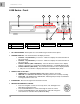
L200 Series - Back L200 Series - Back 1 1 2 3 2 LAN Port VGA Port Video OUT 3 4 4 5 6 5 Audio IN/OUT Video IN PS/2 Port 6 7 8 7 8 Alarm Block RS-485/PTZ Block 9 10 9 10 Power Input Power Switch 1. ETHERNET CONNECTION – Connects the DVR to a router for connection to the Local Network and Internet. 2. VGA VIDEO OUTPUT – Video Output port to connect the unit to a Computer Monitor. Directly reflects the current onscreen images. 3.
Remote Control Listed below is a quick reference for the Remote Control. All Buttons described above function the same as the Front Panel buttons. 1. REC BUTTON – Starts manual recording on the DVR. 2. ONE FRM BUTTON – Not Used. 3. CH4 ◄ BUTTON – Press to view QUAD2 (CH5~8 in L208 Series Only). 4. QUAD/ENTER BUTTON – Press the ENTER Button to select and change the values in a menu. Pressing the ENTER Button when displaying live video will change the onscreen view to 8 Channel View (L208 Series Only). 5.
Mouse Control Mouse Control A mouse can be used with this DVR for Playback and Menu controls. Connect a mouse to the PS/2 port located on the back of the unit before powering the unit ON. Once the unit has loaded, the mouse will be recognized by the system. Mouse Controls DVR Setup • • • • • The Setup window is displayed when the right mouse button is clicked in viewing mode. When the mouse is moved, the purple highlight box will switch between menu options.
Camera Installation Before you install the camera*, carefully plan where and how it will be positioned, and where you will route the cable that connects the camera to the DVR. Installation Warnings: • • • • • Select a location for the camera that provides a clear view of the area you want to monitor, which is free from dust, and is not in line-of-sight to a strong light source or direct sunlight.
Connecting BNC Cameras Connecting BNC Cameras 1. Connect the 60ft Extension cable to the Camera and DVR: A. Connect the Barrel Power connector to a power adaptor. B. Connect the BNC connector to an available BNC Port (CAM 1~4) on the DVR. C. Connect the Male Power connector to the Camera. D. Connect the BNC connector to the Camera. Connect to DVR and Power Adaptor 2. Connect the Power Adaptor to a wall outlet.
Display Modes Initial Loading Sequence The unit will automatically begin loading when power is connected to the DVR, and the ON/OFF button on the back of the unit is switched to ON. 1 1. The DVR will perform a Firmware check.
Display Modes General Display Overview 1. CAMERA TITLE & RECORDING STATUS - Displays the Camera Name (Up to 8 Characters) and Displays the current Recording Status (if the System is recording the □ symbol appears). 1 CH1 CH2 CH3 CH4 2 2. VIDEO LOSS ICON - Appears when the Camera is not sending a Video Image. 4. DRIVE FULL INDICATOR – Indicates the amount of drive space available (100% indicates full). If the circle with arrows (4) is displayed the DVR is in Overwrite Mode. 5.
CH5 CH6 CH7 CH1 CH2 CH3 CH4 CH5 CH6 CH7 CH8 CH8 100%4 07/01/01 01:02:03 QUAD2 (CH 5~8) – Press the CH5 button to display the Quad View. 100%4 07/01/01 01:02:03 9-CHANNEL VIEW – Press the ENTER Button to display all cameras (L208 Series) Onscreen Symbols – Channel Symbols The following symbols appear on a channel to indicate the status of the channel: Indicates that the channel is currently Recording video. Indicates that Motion has been detected on the channel.
System Setup Controls System Setup Controls • Enter the SYSTEM MENU screen by pressing the MENU/EXIT button. Enter the password to display the Menu Selection Screen. • Scroll through the 11 options by pressing the UP & DOWN (▲▼) buttons on the Front Panel or Remote Control. • To enter a sub-menu, navigate to the option (indicated by the Purple Hightlight) and press the ENTER Button ( ↵ ). • To exit a SUBMENU, press the MENU/EXIT button. • To change the options, press the RIGHT and LEFT buttons (◄►).
System Menu Tree SETUP CAMERA CHANNEL DISPLAY BRIGHTNESS CONTRAST HUE SATURATION RECORD RECORD SPEED RECORD QUALITY EVENT REC DURATION RECORD SCHEDULE REC SCHED ENABLE SENSOR ALARM DURATION SENSOR 1 SENSOR 2 SENSOR 3 SENSOR 4 MOTION DETECT CHANNEL SENSITIVITY ALARM DURATION MOTION AREA SCREEN BOARDER VIDEO ADJUSTMENT SEQUENCE INTERVAL 21 ENG System Setup Controls
System Setup Controls MAIN MENU AUDIO RECORD MUTE INPUT VOLUME OUTPUT VOLUME SYSTEM HARD DISK SETUP PASSWORD CHANGE PASSWORD ENABLE TIME SET SYSTEM EVENT LIST NETWORK RS-485 PAN \ TILT DEVICE F/W UPGRADE SEARCH TIME SEARCH NORMAL RECORD TIME RECORD MOTION RECORD SENSOR RECORD TOTAL RECORD EVENTS BACKUP STATUS FACTORY DEFAULT EXIT 22
Using the Virtual Keyboard The Virtual Keyboard control becomes available when keyboard input is needed for entering information such as Names, Network Information, etc. • • • • Includes a~z, A~Z, 0~9 and Symbols: !@#$%^&*()_+{}<>?-=[];,./ Navigate using the arrow keys ▲▼◄► on the Front Panel or Remote Control.
System Setup Controls RECORD SETUP The Record Setup controls the settings for Recording for the DVR. Use the ▲▼ arrows to navigate through the settings, and the ◄► arrows to change the values. Press the MENU/EXIT button to return to the previous menu. RECORD QUALITY Set the RECORD QUALITY to LOW, NORMAL or HIGH. This setting is the same for all channels.
RECORD SCHEDULE RECORD SCHEDULE ENABLE Sets the Recording Schedule to ON or OFF. NOTE: It is important to leave this setting to ON. If this setting is turned OFF, the DVR will NOT record any data (Manual Recording (when the REC Button is pressed) will override the Record Settings, and immediately begin recording.
System Setup Controls MOTION DETECTION SETUP The Motion Detection Setup controls the behavior of the DVR when Motion is detected. Use the ▲▼ arrows to navigate through the settings, and the ◄► arrows to change the values. Press the MENU/EXIT button to return to the previous menu. MOTION AREA SUBMENU Use the Motion Detection area to determine which areas of the image will detect motion. Areas shaded with a darker color indicate that the area is selected to detect motion.
SCREEN SETUP AUDIO SETUP The Screen Setup controls the onscreen display of the DVR. The Audio Setup adjusts the input/output of the DVR system. Use the ▲▼ arrows to navigate through the settings, and the ◄► arrows to change the values. Press the MENU/EXIT button to return to the previous menu. Use the ▲▼ arrows to navigate through the settings, and the ◄► arrows to change the values. Press the MENU/EXIT button to return to the previous menu.
System Setup Controls SYSTEM MENU The System Setup controls many aspects of the functionality in the DVR, including the Password, Time and Date, Network and PTZ setup. OVERWRITE – If the Overwrite option is set to Yes, when the Hard Drive becomes full the system will begin overwriting the older information. If Overwrite is set to No, then the DVR will stop recording when the Hard Drive becomes full. Use the ▲▼ arrows to navigate through the settings, and the ◄► arrows to change the values.
PASSWORD ENABLE SYSTEM EVENT LIST SUBMENU The Password Enable feature turns the use of a system password ON or OFF. If the option is set to YES, the password is required when entering the Setup Menu, Resetting Factory Defaults, Using the PTZ and Stopping video recording. The Event List provides a detailed listing of the events that have occurred in the system. SYSTEM MENU TIME SET SUBMENU The Time Set menu controls the date and time for the DVR.
System Setup Controls NETWORK SUBMENU The information in the Network submenu allows users to remotely access the DVR. ENABLE – Set Enable to YES to remotely connect to the DVR over a network connection. If this option is set to NO, remote access to the system will be disabled. LOCAL IP MENU – The Local IP menu contains the IP Address and other networking information. DHCP SETUP NOTE: The Local Network will lease the information to the DVR. The user is not required to complete these fields.
STATIC SETUP Use the arrow buttons to change the Network Settings: PPPOE SETUP NOTE: Gather the Network and PPPOE Information prior to changing these settings. • • • • • • IP Type: Static IP Address: Enter an IP address that is not currently in use on the local network. Gateway: Enter the Gateway for the local network. Net Mask: Enter the Subnet Mask information for the local network. PPPOE ID: Press the Enter button to display the virtual keyboard window.
System Setup Controls NETWORK SUBMENU (CONT.) DDNS SETUP PORT – The Port Information is required for remote access. The default port for the DVR is 8841. Please refer to the Port Forwarding section of this manual for details. • • MAC ADDRESS – The Mac Address is the unique physical address set by manufacturer, which is necessary for DDNS network connection. Do not change this value. Enable: Set to YES if using the DDNS Service. DDNS ID: DDNS SERVER SET-UP (ENABLE): Select “YES” in name server set-up.
RS-485 SUBMENU PAN/TILT DEVICE SUBMENU The information in the RS-485 submenu allows users to configure the settings for an RS-485 Device. NOTE: The configuration settings for this section would be provided with the documentation included with the PTZ Camera. • • • • CHANNEL: Select the Channel where PTZ camera is connected. ID: Assign the specific ID of the PTZ camera. MODEL: Select the model of PTZ camera. PAN/TILT TEST: Test PTZ Camera.
System Setup Controls SEARCH MENU The Search Menu contains a list of submenus to search through previously recorded video. Use the ▲▼ arrows to navigate through the settings, and the ◄► arrows to change the values. Press the MENU/EXIT button to return to the previous menu. • • • • • • • TIME SEARCH: Searches for video based on Time and Date. NOMAL RECORD EVENT: Searches for video that was recorded manually (using the REC button). TIME RECORD EVENT: Searches for video that was recorded on a schedule.
RECORDING symbol, it When a Channel is displaying a indicates that the channel is in record mode. Recording Schedule Symbols: White (No Recording) Red (Continuous Recording): The DVR is constantly recording, and does not detect Motion or Sensor events. Green (Motion Detection Recording): Begins recording when Motion is detected, and does not record continuously or when a sensor event occurs.
SEARCH FUNCTION SEARCH FUNCTION There are several ways to access the Search Function: • From the Main Menu / Search Menu • Pressing the PLAY Button • Pressing the SEARCH Button Time Search However, each Search menu contains different search options: Main Menu / SEARCH Button Menu • • Start: Displays the Date and Time for the first available recording. End: Displays the Date and Time of the last recording. Press the Enter Button To set the Date and Time.
SEARCH TYPES • • • • • • • TIME SEARCH: Searches for video based on Time and Date. NOMAL RECORD EVENT: Searches for video that was recorded manually (using the REC button). TIME RECORD EVENT: Searches for video that was recorded on a schedule. MOTION RECORD EVENT: Searches for video that was recorded when motion was detected. SENSOR RECORD EVENT: Searches for video that was recorded during a sensor event. TOTAL RECORD EVENT: Displays all recorded video.
VIDEO PLAYBACK VIDEO PLAYBACK BACKUP FUNCTION There are two methods to backup video data: • To a USB Memory Stick • To a Blank CD The L200 Series DVR can play previously recorded video onscreen, while still recording live video images. BUTTON PLAY / PAUSE REC FF REW STOP DESCRIPTION Playback of previously recorded data / Pauses the data playback Start manually recording / Stop recording Fast Forward the video playback. Press the FF button to change playback speed to 2x, 4x or 8x speed.
BACK-UP VIA CD-R/W (OPTION) To save video to the USB Memory Stick, set the start and end times for the selection: • Press the ▲▼ buttons to set the backup starting and ending points • The Available Disk Space and copy size are shown in KB • Press the SEARCH or REC button to start the backup. If the data size is larger than 600MB, the message “DATA SIZE IS BIG TO COPY” is displayed onscreen. Use the ▲▼◄► Arrow keys and Enter Button to change the Starting and Ending Date and Time.
FIRMWARE UPGRADE FIRMWARE UPGRADE The DVR supports upgrading the Firmware through a USB Memory Stick. 1. Download the new firmware from http://www.lorexcctv.com to the PC. 2. Copy the firmware files to a USB Memory Stick. 3. Insert the Memory Stick into a USB Port on the DVR. 4. Navigate through the System Menu: SETUP Menu => SYSTEM Menu => F/W UPGRADE. NOTE: If the system is actively recording, the Firmware Upgrade cannot take place.
PTZ (PAN/TILT-ZOOM) This DVR supports a PTZ Camera via the RS485 Serial Interface (see Appendix #6 for details). Press the PTZ button in Live Monitoring mode to enter PTZ control mode. PTZ control buttons include: Button PTZ UP RIGHT DOWN LEFT FF REW CH1~8 (Select PTZ camera) Description Enter / Exit PTZ mode. Moves the camera UP. Moves the camera RIGHT. Moves the camera DOWN. Moves the camera LEFT. ZOOM IN ZOOM OUT Select the camera ID for PTZ control. The camera ID is the same as channel No.
Lorex Client Application Lorex Client Application The L200 Series DVR comes with the Lorex Client application for remote monitoring, recording, DVR control or playback of video data on a PC. The Lorex Client Application has two components: • Player Mode: Used to view video data from a backup device such as a USB Memory Stick or CD-RW. • Viewer Mode: Used to remotely connect to the DVR.
PLAYER MODE The Player Mode is used to view video data from a backup device such as a USB Memory Stick or CDRW. PLAYBACK METHOD To view video data, first connect the USB memory stick to the PC or place the CD into CD/DVD Drive. Once the backup data is connected to the PC, start the Lorex Client program Click the Player icon on the top of the Lorex Client program to switch to Player mode. Click the icon on the lower left side of the player.
Lorex Client Application PLAYER MENU PLAYBACK The playback menu includes buttons for: • Play • Reverse • Pause • Fast Forward • Fast Rewind • Next Frame • Previous Frame • Speed Normal • Speed Up • Speed Down These function buttons are arranged along the bottom of player program.
Capture The Capture function can be used to save parts of the video to the local hard drive. Click the Export link to save the selected video to a *.VVF file. Click the Mark In link at the starting point and Mark Out at the end point. • • • Click the Browse button to assign a Save location. Click the Do Export button to save the video to the local hard drive. Click the Close button to exit the window.
Lorex Client Application AUDIO FUNCTION The Audio Function controls the Audio Volume, and turns the MUTE ON/OFF. Full Screen Select Full Screen to view a single camera in Full Screen mode, or Press Alt+Enter. Double click the upper part of the window to magnify the screen.
Aspect Ratio The screen size can be set to 640x448 or 640x544. Split Mode The Split mode (QUAD) can be set to 1ch full screen, 4ch Quad screen, 9ch split screen.
Lorex Client Application Option Menu The Option Menu includes settings for: • Playback • Date and time format • Save Folder General Options • • • • • • 48 Always on top: Highest level on window Use DirectDraw: Use the applied program interface (API) included in Direct X. Show playback time: Set to show the playback time on the screen. Repeat playback: Repeat Playback On screen display date/time format: Set the date/time format on the screen. Path for still capture: Set the path for still capture.
Export Save video data backup as an AVI format on the computer. • • • • Select the video data to backup (select Input File). Select a location and a name for the saved file (select Output File). Select the Compression type on the Compression Select menu, and click OK Click the Export Channel OK button, and the program will save the file. The Image file (AVI) is saved per channel.
Lorex Client Application Close Viewer To close the Viewer, click the EXIT button, or click the X button on the top-right side of program to close. BUTTON FUNCTION You can click the buttons shown below on the program to perform the matching function, or use the shortcut keys listed. ICON 50 SHORTENING KEY FUNCTION F2 Open and play video file. R Rewind. B Play Reverse. Z Go one frame backward and Pause. P Pause. X Go one frame forward and PAUSE.
G Playback. F Fast Forward. - When you click this button, it will take a single frame of video image while playback and then it will automatically save the image. (BMP format) into the local PC directory (Initial folder setup : “C:\VxCapture”) - View in 1-channel full screen mode. - View in 4-channel screen mode. - View in 8-channel screen mode. - Search symbol for HDD connection. - Mark In - Mark Out - Export Adjust volume or enable speaker sound ON/OFF.
Lorex Client Application VIEWER MODE The DVR can be viewed remotely using the Viewer portion of the application. CONNECTING WITH VIEWER To monitor the DVR through the VIEWER program, check that a network connection between the DVR and PC can be established. The Viewer program can be used to connect to the DVR on the Local Area Network (LAN), or remotely through the Internet (WAN). Launch the Lorex Client program.
CONNECTING ON THE LAN (LOCAL CONNECTION): To connect to the DVR on the LAN, press the REW button on the DVR to get the local IP address (i.e. 192.168.0.104). Enter the following information on the connection window: • IP Address: The IP of the DVR (i.e. 192.168.0.104) • Port: Enter 8841 (default) • Password: Enter 111111 (default password. If the password has been changed on the DVR, use the changed password). • Click the CONNECT Button to view the DVR.
Lorex Client Application VIEWER MENU DVR Control The DVR can be controlled through the Viewer portion of the Lorex Client application.
Audio The Audio option controls the Volume, and setting the mute to ON or OFF during playback. Local Recording The live video stream can be saved to the connected PC using the viewer program. Click the Local Recording -> Start Local recording menu to begin saving the data. Click the Stop Local Recording menu to end the data save to the local PC. Video image files will be saved to the directory set in Options (the Default Directory: C:\VxCapture).
Lorex Client Application Full Screen To change the screen to Full Screen mode, select the FULL SCREEN option or press ALT+F4. Double click on the upper port of program to maximize the screen. Aspect Ratio The screen size can be set to 640 X 448 or 640 X 544.
OPTION FUNCTION The option menu includes: • Repeat playback • Connection Attempts • Auto Reconnection • The save folder for video GENERAL OPTIONS • • • • • • Always on top: Places the window at the top of the screen. Use DirectDraw: Use the applied program interface (API) included with Direct X. Auto Reconnection: Attempts to reconnect with the DVR when the connection fails. Repeat playback: Repeats the playback. Connection Timeout: Set a time for connection timeout.
Lorex Client Application Close Viewer To close the Viewer, click the EXIT button, or click the X button on the top-right side of program to close. BUTTON FUNCTION You can click the buttons shown below on the program to perform the matching function, or use the shortcut keys listed. ICON 58 SHORTENING KEY FUNCTION L Connect /Disconnect DVR. - Save present screen G Play/Pause. R Rewind. F Fast Forward. S Stop. C Record.
• • •• Up, Down, Left, Right. Enter key Enter / Select M Menu / Exit - Time Search.
DVR Specifications - Appendix #1 DVR Specifications - Appendix #1 Feature L204 series L208 series Operating system Real-time (RTOS) Real-time (RTOS) Video Input 4 Channel (BNC) 8 Channel (BNC) 2 Channel (2-composite/1VGA) 3 Channel (2-composite/1VGA) NTSC / PAL NTSC / PAL Video Output Video Input Standard Monitoring Resolution NTSC 720 * 480 Pixels 720 * 480 Pixels PAL 720 * 576 Pixels 720 * 576 Pixels Recording Resolution NTSC 640 * 224 Pixels 640 * 224 Pixels PAL 640 * 272 Pixels
DVR Specifications - Appendix #1 Continuous / Motion/Schedule/sensor Continuous / Motion/Schedule/sensor HDD * 2 (Max 500GB ea = 1TB) HDD * 2 (Max 500GB ea = 1TB) ON / OFF Control ON / OFF Control 1 Ch. 1 Ch.
Full Connectivity Diagram – Appendix #2 Full Connectivity Diagram – Appendix #2 The following diagram outlines a general set of connections available with the DVR*. BNC CAMERAS MOUSE DVR PC MONITOR SLAVE MONITOR, TV OR OBSERVATION SYSTEM * All components shown above (other than the DVR) are not included.
Hard Drive Replacement - Appendix #3 The DVR comes with a pre-installed Hard Drive; however the unit will work with a replacement single IDE Hard Drive (up to 500GB). A maximum of two (2) Hard Drives can be installed into the DVR; however the CD-RW must first be disconnected. The Hard Drive storage capacity and model name are shown on the loading screen when the DVR system loads. If the DVR does not recognize the Hard Drive, the system will not boot.
Hard Drive Replacement (cont …) Hard Drive Replacement (cont …) Installing the New Drive • • • Place the new drive in the case, and reattach the holding screws. Reconnect the cables in the same way as connected to the previous drive. o Reconnect the IDE Cable. Confirm that the cable is securely connected within the DVR and to the Hard Drive. o Reconnect the Hard Drive power cable. Confirm the cable is securely connected to the Hard Drive.
Troubleshooting – Appendix #4 When a malfunction occurs, it may not be serious and can be corrected easily. The following describes the most common problems and solutions. Please refer to the following before calling Lorex Technical Support: Problem: DVR Unit is not receiving power, or is not powering up Check: • Confirm that all cables are connected correctly. • Confirm that the power adapter is securely connected to the back of the unit.
Troubleshooting (cont…) Troubleshooting (cont…) Problem: The picture on the DVR is poor, shrinks or flickers Check: • Check the camera video cable and connections • Disconnect and reconnect the cable at the DVR and at the Camera • Clean the camera lens • Adjust the CONTRAST and BRIGHTNESS settings in the Menu • Check that the Camera is not in direct sunlight Problem: There is no picture appearing on a Channel / Camera is not displaying Check: • Check the camera video cable and connections • Disconnect and
Appendix #5 – Network Connectivity Overview The DVR can be remotely controlled using your existing network and the provided software. 1. Connect the DVR to the Router using an Ethernet Cable. Power the DVR on. NOTE: The DVR must be connected to the router prior to powering on the system. This allows the DVR to communicate on your network 2. Find the IP address of your DVR through the Menu System on the unit. See the Menu section of this manual for additional System Settings. 3.
Appendix #5 – Network Connectivity Overview IP & MAC Address (Step #2) The IP & MAC Addresses are necessary for DDNS Setup (for remote access to the DVR). To Locate the System information, Press the REV Button on the Front Panel or Remote Control while viewing the Cameras. The System Info window will be displayed. - OR - 1. Press the Menu Button on the Front Panel or Remote Control to access the Setup Menu. Select the System Menu option and press the Enter button. 2.
Setting Up Your DDNS Account (Step #3 Cont …) 3. Complete the Account Information fields with your personal information 4. Complete the System Information fields: • Product License: Select your product model from the Product License drop down menu • - : Locate the MAC address of your (recorded while loading the System) • URL Request: Choose a URL for your DDNS connection (i.e. your name, your company or business name, or anything of your choice.
Appendix #5 – Network Connectivity Overview Router Port Forwarding (Step #4) You will need to enable port forwarding on your Router to allow for external communications with your Observation System for ports: • PORT 8841 Computers, DVRs, and other devices inside your network can only communicate directly with each other within the internal network. Computers and systems outside your network cannot directly communicate with these devices.
DDNS Setup on the DVR (Step #5) Once the DDNS settings have been configured online, the information must be entered on the DVR to allow for remote connection via the Software: 1. Access the Setup screen by pressing the MENU button on the front of the DVR. Navigate to the SYSTEM option, and press the ENTER button to access the System Setup. 2. Navigate to the NETWORK option, and press the Enter button to access the Network settings.
Appendix #6 – PTZ Control Appendix #6 – PTZ Control One PTZ Camera (not included with this system) can be connected to the PTZ Control Block on the back panel of the DVR, and are enabled through the Menu system. Additional PTZ Cameras are available at http://www.lorexcctv.com Installing a PTZ (RS-485 Type) PTZ Camera: 1. Connect the Transmit Cable to the 485+ port on the PTZ Control Block. 2. Connect the Receive Cable to the 485- port on the PTZ Control Block. 3. Connect the Camera to BNC Channel 1. 4.
Appendix #7 – Connecting Motion / Alarm Device Motion detection and Alarm controls are enabled through the Menu system on the DVR. Additional motion sensor devices can be connected to the system (Motion Sensors, Door/Window Sensors). A motion detection or sensor unit can be used to send a signal to the DVR to begin camera viewing and recording on the matching Video Channel (when enabled in the Menu) • Example: A Window sensor unit has been installed on Alarm Block port #4.
Appendix #8 – Initial Setup Menu Values Appendix #8 – Initial Setup Menu Values SETUP CHANNEL DISPLAY CAMERA BRIGHTNESS,CONTRAST,HUE,SATURATIO N RECORD SPEED RECORD QUALITY RECORD EVENT REC DURATION RECORD SCHEDULE RECORD SCHEDULE ENABLE ALARM DURATION SENSOR SENSOR1/2/3/4 CHANNEL MOTION SENSITIVITY DETECTION ALARM DURATION MOTION AREA BORDER SCREEN VIDEO ADJUSTMENT SEQUENCE INTERVAL RECORD MUTE AUDIO INPUT VOLUME OUTPUT VOLUME SYSTEM HARD OVERWRITE ENABLED DISK SETUP FORMAT HDD PASSWORD CHANGE PASSWORD EN
DDNS SETUP ENABLE DDNS ID DDNS PASSWORD DOMAIN NAME STATUS RS485 PAN/TILT DEVICE F/W UPGRADE SEARCH STATUS FACTORY DEFAULT EXIT VIDEO QUALITY BAUDRATE DATA BIT PARITY BIT STOP BIT CHANNEL ID MODEL PAN/TILT TEST NO HIGH 115200 8 NONE 1 1 1 NONE - EXIT&SAVE CHANGES EXIT&DISCARD CHANGES - 75 ENG Appendix #8 – Initial Setup Menu Values
Appendix #9 – HDD Usage Table Appendix #9 – HDD Usage Table The following table is provided as an approximation of Hard Drive usage. Variables in image quality and frame rates may alter the hard drive usage.
Optional Accessories The following accessories are available to add to your existing DVR BNC DOME TYPE CAMERAS BNC CAMERAS CAMERA EXTENSION CABLES NIGHT VISION ACCESSORIES CAMERA ADAPTOR CABLES To order these accessory items, or for a complete listing of available products, please visit us on the web at: WWW.LOREXCCTV.
It’s all on the web Product Information Specification Sheets User Manuals Software Upgrades Quick Start Guides Firmware Upgrades VISIT www.lorexcctv.com www.lorexcctv.com Lorex Technology Inc.