PROFESSIONAL 19” LCD OBSERVATION SYSTEM WITH BUILT-IN 8 CHANNEL DIGITAL VIDEO RECORDER Instruction Manual English Version 5.0 MODEL: L19LD800 Series www.lorexcctv.com Copyright © 2007 Lorex Technology Inc.
Thank you for purchasing the LCD / 8 Channel DVR Combo. Lorex is committed to providing our customers with a high quality, reliable security product. This system offers a whole new level of security surveillance to the consumer market.
Important Safeguards Important Safeguards In addition to the careful attention devoted to quality standards in the manufacture process of your video product, safety is a major factor in the design of every instrument. However, safety is your responsibility too. This sheet lists important information that will help to assure your enjoyment and proper use of the video product and accessory equipment. Please read them carefully before operating and using your video product. Installation 1.
Important Safeguards Service Use 12. Servicing - Do not attempt to service this video equipment yourself as opening or removing covers may expose you to dangerous voltage or other hazards. Refer all servicing to qualified service personnel. 18. Cleaning - Unplug the video product from the wall outlet before cleaning. Do not use liquid cleaners or aerosol cleaners. Use a damp cloth for cleaning. 13.
General Precautions General Precautions 1. All warnings and instructions of this manual should be followed 2. Remove the plug from the outlet before cleaning. Do not use liquid aerosol detergents. Use a water dampened cloth for cleaning 3. Do not use this unit in humid or wet places 4. Keep enough space around the unit for ventilation. Slots and openings in the storage cabinet should not be blocked 5.
L19LD800 Series Features L19LD800 Series Features • • • • • • • • Internet Remote Viewing*, Backup and Control utilizing a web browser or client software (included) ‘True’ 8 Camera digital video system with Triplex operation allows you to View, Playback and Record video simultaneously Thin design 19” LCD surveillance display features ultra-fast refresh rate with mouse driven navigation and multi-lingual on screen display High Reliability Surveillance Hard Disk Drive with MPEG4 video compression** Hard Dri
Table of Contents Table of Contents Getting Started .............................................................................................................................................. 9 L19LD800 Series - Front............................................................................................................................. 10 L19LD800 Series - Back .............................................................................................................................
Table of Contents Table of Contents Archive Menu .............................................................................................................................................. 39 Camera Menu ............................................................................................................................................. 40 Display Setup Menu ....................................................................................................................................
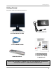
Getting Started Getting Started The system comes with the following components: 1 x LCD & DVR COMBO UNIT WITH PRE-INSTALLED HDD 1 x POWER ADAPTOR 1 x 10’ ETHERNET CABLE REMOTE CONTROL 1 x HARDWARE MANUAL 1 x SOFTWARE MANUAL 1 x QUICK START GUIDE 1 x INSTALL CD CHECK YOUR PACKAGE TO CONFIRM THAT YOU HAVE RECEIVED THE COMPLETE SYSTEM, INCLUDING ALL COMPONENTS SHOWN ABOVE.
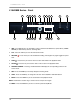
L19LD800 Series - Front L19LD800 Series - Front 1 2 3 14 15 13 4 5 16 17 6 7 18 8 19 9 11 10 20 21 12 22 1. USB - Two USB 2.0 ports are provided to connect external hard disk drives, optical drives (CDRW / DVDRW) or USB memory stick for archiving video. 2. PTZ - Press the PTZ key to enter the PTZ control mode. 3. RECORD start. 4. STOP 5. PAUSE - Press the key to start scheduled recording.
L19LD800 Series - Front L19LD800 Series - Front 1 2 3 14 15 13 4 5 16 17 6 18 7 8 19 9 11 10 20 21 12 22 11. STATUS INDICATOR LEDs - LEDs will illuminate when the following occur: • IR RECEIVER (does not illuminate) - Receives the signal from the IR transmitter on the Remote Control. • RECORD LED - Illuminates when the unit is in Record Mode. • NETWORK LED - Illuminates when a remote user is connected to the unit (Network Access).
L19LD800 Series - Front L19LD800 Series - Front 1 13 2 3 14 15 4 5 16 17 6 18 7 8 19 9 11 10 20 21 12 22 18. NAVIGATION & VOLUME CONTROLS – The Volume Controls are used in Live Viewing & Playback Modes: • VOL + (RIGHT) Press the VOL + (Volume UP) key to increase the volume level in the live screen 16 mode. • VOL– (LEFT) Press the VOL– (Volume DOWN) key to decrease the volume level in the live screen mode.
L19LD800 Series - Front L19LD800 Series - Front 1 2 3 14 15 13 4 5 16 17 6 18 7 8 19 9 11 10 20 21 12 22 22. PTZ - ALTERNATE FUNCTIONS – The following buttons are used in PTZ Mode: - Press to zoom in. • ZOOM IN • ZOOM OUT - Press to zoom out. - Press to control the focus (near). • FOCUS NEAR • FOCUS FAR - Press to control the focus (far). - Press to control the iris close. • IRIS CLOSE - Press to control the iris open. • IRIS OPEN • SET - Press to store the preset while.
L19LD800 Series - Back L19LD800 Series - Back 1 2 3 4 5 6 1. ALARM I/O & RS-485 TERMINAL – Connection point for external devices: • The Alarm Block is used to connect devices such as a motion sensor, door/alarm sensor, or time lapse VCR for Alarm Recording. Refer to appendicies for Alarm Block Configuration. Alarm devices are not included. • The RS-485 Block is used to connect devices such as a keyboard or a PTZ (Pan/Tilt/Zoom) Camera. Keyboards and PTZ Cameras are not included. 2.
Cable Channel & VESA Standard Stand Cable Channel & VESA Standard Stand The L19LD800 Series stand comes with a built in cable channel to easily organize and conceal wiring. The stand can be removed to mount the monitor directly to other VESA standard mounting brackets. Connect the Power Cable, Cameras, Ethernet Cable and any Alarm Devices to the System by running the cables through the hole in the stand before connecting to the Observation System.
Remote Control Remote Control Listed below is a quick reference for the Remote Control. All Buttons described above function the same as the Front Panel buttons. POWER - Turns the LCD Monitor power ON/OFF CHANNEL BUTTONS Press to select a specific camera by number SEQ - Turns camera Sequence Mode ON/OFF. AUDIO - Press to select a channel for listen-in audio MENU - Opens the Main Menu (system setup).
Camera Installation Camera Installation Before you install the camera*, carefully plan where and how it will be positioned, and where you will route the cable that connects the camera to the System. Installation Warnings: • • • • • Select a location for the camera that provides a clear view of the area you want to monitor, which is free from dust, and is not in line-of-sight to a strong light source or direct sunlight.
Connecting DIN Cameras Connecting DIN Cameras 1. Connect the female end of the supplied extension cable to the camera. NOTE: Confirm that the arrows on the DIN Camera Cable and the DIN Extension cable are pointed together when connecting the cable. If the pins in the DIN Cable are bent, the Camera will NOT function. 2. Connect the male end of the supplied 100’ extension cable to an open DIN camera input (CAM 1~4) on the back of the System. Continue connecting additional DIN cameras.
Connecting BNC Cameras Connecting BNC Cameras 1. Connect the 60ft Extension cable to the Camera and Observation System: A. Connect the Barrel Power connector to a power adaptor. B. Connect the BNC connector to an available BNC Port (CAM 5~8) on the monitor C. Connect the Male Power connector to the Camera. D. Connect the BNC connector to the Camera. 2. Connect the Power Adaptor to a wall outlet.
Connecting a Mouse Connecting a Mouse Connect a mouse to one of the USB ports located on the front of the unit. Mouse Controls The mouse behaves in the same way as a PC mouse - using Left Click, Right Click and Wheel Rotation: Left Click: • Click the left mouse button to select an item. • When in one of the multi-view formats (i.e. 2x2 or 3x3 view), clicking the mouse button on a camera image switches that camera to full screen. Clicking the mouse button again returns to the previous multi-view format.
Display Modes Display Modes Initial Loading Sequence The unit will automatically begin loading when power is connected to the system. 1 1. The System will perform a Hard Drive and Firmware check. During the loading sequence, the System will perform a Hard Drive and Firmware Check. During the loading sequence, the screen will display the message SYSTEM CHECK. 2. Once the system checks are completed, the screen will display the text message INITIALIZING SYSTEM before completing the loading process. 3.
Display Modes General Display Overview 1. TITLE & RECORDING STATUS – Displays the Title of the Camera (set in the System Menu), and the Recording Status: • : Actively Recording • E: Event • C: Continuous • +: Continuous & Event 1 2 2. CAMERA STATUS – Displays the current status of the camera. See below for details. 3. ONSCREEN LEGEND – Displays the Recording Legend for the Cameras. 3 4 4. SYSTEM STATUS BAR – Displays the System status for: • Date & Time – Set in the System Menu.
Display Modes Camera Display Modes Cameras can be displayed in several different modes by pressing the VIEW Button on the front panel of the system, or by pressing the VIEW Button on the Remote Control. To view a single camera, press the corresponding number key on the Front Panel or Remote Control. SINGLE CHANNEL VIEW – Press the corresponding Channel Number to view. QUAD CHANNEL VIEW CAM 1~4 – Press the VIEW button to display the Quad View.
Menu Navigation Controls & Tips Menu Navigation Controls & Tips Menu Navigation Controls • MENU Button – Accesses the setup menu, and returns to previous menu options. • Navigation Controls - Move Up/Down/Left/Right. • Enter Button - Press this button to select and change the values in a menu option. Virtual Keyboard Control The Virtual Keyboard control becomes available when keyboard input is needed for entering information such as Camera Names, Network Information, etc.
System Setup Controls System Setup Controls • Enter the MENU screen by pressing the MENU button. Enter the password (if required) to display the graphical Menu Selection Screen. The Default password is - press ENTER. • Scroll through the 8 options by pressing the UP, DOWN, LEFT and RIGHT buttons on the Front Panel or Remote Control. • To enter a sub-menu, navigate to the option and press the ENTER button. To exit a SUBMENU, press the MENU button. • To exit the MAIN MENU, press the MENU button.
System Setup Controls System Menu Tree SETUP MENU SYSTEM MENU DATE / TIME LANGUAGE USER DISK MANAGEMENT INFORMATION FACTOR DEFAULTS SETUP & UPDATE MANAGER SYSTEM LOG SCREENSAVER EVENT ALARM-IN MOTION VIDEO-LOSS TEXT-IN RECORD SYSTEM EVENT ARCHIVE CAMERA DISPLAY PTZ NETWORK LAN SERIAL DDNS NOTIFICATION SITE 26
System Menu System Menu • • • • • • • • • Date / Time – Set the Date and Time for the system. Language – Select the GUI Language display User – Configure the system users Disk Management – Controls the overwrite and format of the drive Information – Displays the System information Factory Default – Restores the unit to factory presets. Setup & System Update Manager – Updates the system firmware. System Log – Displays a log of events. Screen Saver – Configures the Screen Saver feature.
System Menu Language Setup Set the onscreen GUI language display to English, French of Spanish. User Setup Configure users for the Local System and for Remote Access. • ADMIN – The Admin login has full permissions to the system. Select the PASSWORD SET (Figure 1) option to change the password. • USER – The User login has variable permissions to the system. Select the PASSWORD SET (Figure 1) and ACCESS SET (Figure 2) options to configure the user. Figure 1. Figure 2.
System Menu User Setup (cont.) • NETWORK USER LIST – The Network List allows for 10 Users to be added to the system. Each user has variable permissions to the system. o ID: Enter an ID for the User, using the Virtual Keyboard. o Select the PASSWORD SET (Figure 1) to set the user password. o Select the ACCESS SET (Figure 2) options to configure the users. o Use the NEXT button to switch between Users 1~5 and 6~10.
System Menu Disk Management (cont…) The Disk Management section also displays information about the Internal and USB drives including: • Device Name • Disk Size • Format Button – Formats the drive. All data on the drive is erased. NOTE: If you disconnect the USB cable connected to the USB port or the power from the USB device while mirroring, the system display a warning message and execute an e-mail notification. If the USB cable is disconnected while mirroring, mirrored data might be lost.
System Menu Setup & System Update Manager The Setup & System Setup menu allows the user to create a backup of the system settings, import the system settings, and update the Firmware. To make a backup copy of the System Settings, connect a USB memory stick to the System and select EXPORT. Enter a name for the backup, and select OK. To import previously saved settings, choose the IMPORT option. Select the OK button to load the settings.
System Menu o o o o o o o o o o o o o o o o o o o o o Backup End Backup Fail Backup Cancel Setup Change Time Change (User) Time Change (NTP) Time Change (RTC) Zone Change Clip-Copy Begin Clip-Copy End Clip-Copy Fail Clip-Copy Cancel Disk Hot Format (Internal) Format (USB) System Update Factory Default Disk Full Email Send fail Disk Smart Bad Mirror Fail NOTE: Up to 20,000 events are recorded. Screen Save Setup The Screen Save feature will turn the monitor screen ON/OFF automatically.
Event Menu Event Menu • • • • • Alarm-In – Sets the system notifications and controls when an event is triggered on an Alarm IN device. Motion – Sets the options for Motion Detection and notification. Video Loss - Sets the system notifications when a Video Loss event is detected. Text-In – Sets the options for processing Text-In (i.e. from a Point of Sale machine). System Event – Sets the notifications for system events.
Event Menu Motion Setup Controls the actions when Pixel-based motion is detected on a Channel. • • 34 HOLD TIME – Set the length of time that the event action will occur (i.e. Buzzer, Onscreen display, etc.) CH1~CH8 – Sets the alarm for each channel to ON or OFF. • ZONE – Set the Motion Detection Area for each camera: o Grid: Select blocks in the grid to turn the motion detection area ON or OFF. (Clear = ON, Pink = OFF).
Event Menu Video Loss Controls the actions when a video loss is detected on a Channel. • • • • HOLD TIME – Set the length of time that the event action will occur (i.e. Buzzer, Onscreen display, etc.) CH1~CH8 – Sets the alarm for each channel to ON or OFF. ACTION – Set the behavior for the system when an event is detected on the specified channel: o All: All actions occur o Relay: A relay output will occur to the Alarm-Out function o Buzzer: An audible buzzer will sound when an event is detected.
Event Menu • TRANSACTION – Set the text-in detection fields: o Start: Set the word or characters that indicate the start of a POS transaction. o End: Set the word or characters that indicate the end of a POS transaction. o Delimiter: sets the End of line character. If not entered, the System assumes that “Enter and Line Feed” is the next line. o Ignore: Set any text to be excluded from onscreen display.
Event Menu Disk S.M.A.R.T If the IDE hard disk installed in the system supports S.M.A.R.T. (Self-Monitoring Analysis and Reporting Technology), the status of the installed IDE hard disk is displayed. • • • ON/OFF– Turns the Temperature detection ON or OFF. HOLD TIME – Sets the event hold time from the first detection of the event.
Record Menu Record Menu The recording menu controls the settings for each camera for basic and scheduled recording. • • • • • • • SCHEDULE – See below. RESOLUTION – Set the size of the recorded images to 704 x 480, 704 x 240, or 352 x 240. PRE-EVENT – See below. CH1~CH8 VIDEO – Turns the recording for each channel to ON or OFF. CH1~CH4 AUDIO – Turns the audio recording ON or OFF for channels 1~4 only.
Archive Menu Archive Menu The archive menu allows the user to backup data to a USB Memory Stick or Hard drive, CD-RW or DVD-RW Drive. Note: You can enter the ARCHIVE menu directly from Live monitoring mode by pressing the COPY key on the front panel. • • • • • • • • • • TYPE – Set the archive type to Backup (backup all data for a specific date range) or Clip Copy (select individual video clips).
Camera Menu Camera Menu Controls the settings for individual cameras. • • • • COVERT – Turns the onscreen display of the camera ON or OFF. The camera remains recording when in Covert. NAME – Use the virtual keyboard to set a camera description. BRIGHTNESS / CONTRAST / HUE / SATURATION – Set camera display settings using the slider bars. RESET – Resets the camera to default settings. Display Setup Menu Controls the settings for the Onscreen Display.
PTZ Setup Menu SEQUENCE Control Pressing the SEQ key in the live view mode causes the system to display live channels sequentially. In full screen mode, the system sequences through the cameras and displays them full screen. In the multi screen mode, the system displays the 2x2 live screens sequentially.
PTZ Setup Menu Using the PTZ Camera Controls The system can control cameras with Pan / Tilt /Zoom capabilities. Press the PTZ key on the front panel to enter the PTZ mode and press the button again to exit the PTZ mode. The camera is controlled using the front panel directional control buttons. Press the PTZ key on the front panel. A pop-up channel select window for the PTZ cameras will be displayed. Select the PTZ camera to control by selecting it from the menu. The PTZ icon control mode.
PTZ Setup Menu Preset positions can be set for the PTZ cameras. Press the to establish Presets and enter a preset number. Press the OK button to save new settings or the CANCEL button to cancel new settings. You can quickly move a PTZ camera to Preset position. Press the Preset position and enter a preset number. to view an established camera A Mouse can be used for easier PTZ control. Position the mouse pointer at the bottom of the screen in PTZ mode, and the following PTZ toolbar will display.
PTZ Setup Menu Pressing the PTZ key on the front panel when in PTZ mode will display the PTZ function window as shown below. Expanded PTZ features are controlled in this mode. The Presets for PTZ can be configured or run in this window. The PRESET field enables PTZ camera related configurations such as controlling the direction, zoom, and iris. A maximum of 999 presets can be saved. Enter a preset number then, press the OK button.
Network Setup Menu Network Setup Menu Controls the network settings for: • • • • • LAN – Network settings for the System SERIAL – Controls for serial devices (i.e. POS input). DDNS – Settings for remote access over the internet NOTIFICATIONS – Automatic email or network notification when an event occurs SITE – Controls the site specific settings. LAN Setup Controls for the System network settings • • TYPE – Set the network setting detection to Manual or DHCP.
Network Setup Menu Serial Setup Controls for the Serial setup for PTZ, Specialty Keyboard or Point of Sale (POS) system. • • USE – Set the device connected to the serial port to PTZ, Keyboard or POS. PORT – Contains the port specific settings. Please refer to the manual for the specific device for details: o Baud Rate o Parity o Data Bit o Stop Bit NOTE: If you select PTZ (RS-485), you can’t use POS or REMOTE (RS-232). DDNS Setup Controls for the settings for DDNS Remote connection.
Network Setup Menu Notification Setup This menu enables notification of event information to Email or Network when an event occurs. • • • • • EMAIL SENDER – Set the email address to appear as the Sender when an email is received. RECEIPIENTS – Set the list of email addresses to receive an email when an event occurs. INTERVAL – Set the notification interval between emails LIMIT- Set the maximum number of emails to be sent for a particular event.
Network Setup Menu Network Notification: The Network Notification feature sends an alert from the System to the remote client software (up to 5 instances of the Software Client). This feature is designed to work on the Local Area Network. 1. Run IPCONFIG on the PC with the installed Software Client to get the IP Address. 2. Set the IP Address location of the Lorex Client Software (The PC to receive the event notification) on the Network Notification screen. These sites are part of the NETWORK section.
Additional Key Functions Additional Key Functions Key Add Function Pressing the Fn key on the front panel will display the key add function window. PANEL ADJUST You can configure the brightness and contrast of the LCD panel. Pressing the SET item displays a control bar at the bottom of the live screen as follows. Press the MENU or Fn key to exit the LCD adjust mode. EVENT RESET Selecting “EVENT RESET” in the function screen causes the system to reset both the Alarm Output signal and the internal buzzer.
Additional Key Functions SNAPSHOT You can capture and save a still cut in the pause mode during the playback. First, insert the USB memory stick to the USB port in the front panel. Then, play a video and set screen mode to full screen for the channel you want to capture. After that, press the pause button in the capture position of video. Finally, Select SNAPSHOT in KEY ADD FUNCTION menu to capture and save a still cut. This function is inactivated in the live monitoring mode or multi-screen playback mode.
Playing Recorded Video Playing Recorded Video If a user with Search authority logs into the system, the user can view recorded video. Once video has been recorded, you can view it by pressing the PLAY, key on the front panel. • When playing video for the first time, the system will display the most recently recorded video. • When playing video any other time, the system will start playing video from the last image. Recorded audio will be played while the system displays the camera with recorded audio.
Playing Recorded Video Mouse Usage The mouse can be used for easy playback control. Position the mouse pointer at the bottom of the playback screen, and the following search toolbar will display. on the left side exits the toolbar. To display the toolbar again, position the mouse pointer at Clicking the bottom of the playback screen.
Video Search Video Search Pressing the SEARCH key on the front panel or the remote control enters the Search mode while in the Live monitoring mode or in the Playback mode. The Search function window will be displayed. Select SOURCE to search from the beginning. GO TO THE FIRST Select “GO TO THE FIRST” in the search function menu. This function displays the first recorded image. GO TO THE LAST Select “GO TO THE LAST” in the search function menu. This function displays the last recorded image.
Video Search CALENDAR SEARCH Select the “CALENDAR SEARCH” option in the search function menu. A basic search screen will be displayed as shown below. • • • • Select the CHANNEL, ITEM and MONTH to search. Days with recorded video display on the calendar with red numbers. Highlight the days with recorded video by using the arrow buttons. Once a day has been highlighted, press the ENTER, key to select, and a time table window will be displayed as shown below.
Video Search NOTE: The 24 hours time table has 24 one-hour segments. Each segment consists of 24-numeric blocks which are ranged from 0 to 23. If a number is highlighted in Red, it means that video was recorded during that hour. However, it does NOT mean video was recorded for the entire hour. NOTE: The 60 minutes time table has six 10-minute segments. Each segment consists of 10-numeric blocks which range from 0 to 9.
Video Search • • • • Pressing the ENTER, key will extract the event video and display the first image of the event. Pressing the PLAY, key will start playing the “event” video segment. Pressing the STOP, key causes the system to return to live monitoring mode. The Event Search can be further refined by selecting the OPTION button and setting up the new search condition. • The Video can be searched from the first to last recorded images, or by using the start and stop times and dates.
Video Search TEXT-IN SEARCH The Text-In Search allows the user to search for a recorded video initiated by a Text-In input (such as a POS device). • • • Select TEXT-IN SEARCH in the search function menu to display a Text-In search window as below. Selecting an event in the list will play a video of the chosen date and time. Selecting the FROM and TO field will allow the user to manually change the time to be searched. If the KEYWORD fields are blank, all the Text-In events are searched.
Video Search • • • • Press the DETAIL button to overlay the text-in data on the video during the Text-In playback. Pressing the MENU key while in the On-Screen Text-In playback mode returns the system to the Text-In search mode. Pressing the PLAY, key while in the Text-In search mode returns the system to the Playback mode and exits the Text-In Search mode. Press the MENU key to exit the Text-In search mode. NOTE: The video in the Text-In playback mode is played at regular speed.
Observation System Specifications - Appendix #1 Observation System Specifications - Appendix #1 Operating System Language Storage Data Export Medium Data Backup Disk Management Video Source Video Input Video Resolution Display Rate Compression Method Recording Rate Playback Rate Recording Mode Search Mode Connection Protocols Remote Software Alarm Input Alarm Output Audio In / Out IR Port User Interface USB Port RS232C Serial Port RS485 Serial Port LCD Panel Active Display Area ( Diagonal ) Pixel form
Observation System Specifications - Appendix #1 Pixel Pitch Color Depths Contrast Ratio Brightness Viewing Angles (Left/Right/Up/Down) Light Source / Lifetime Response Time ( Tr / Tf ) Dimensions (W x H x D) Weight Operation Environment Power (AC input) Approval 60 0.294mm X 0.294mm 16.7M Colors 1000 : 1 ( Typical ) 300cd / m2 80˚ / 80˚ / 80˚ / 80˚ (Typical) 4CCFT / 50,000 Hours ( Minimum ) 1.5/3.5ms (Rising / Falling) GENERAL 568 mm x 638 mm x 310 mm (Including Packing Ass’y) 19.
Connecting Motion / Alarm Device - Appendix #2 Connecting Motion / Alarm Device - Appendix #2 Motion detection and Alarm controls are enabled through the Menu system on the Observation System. Additional motion sensor devices can be connected to the system (Motion Sensors, Door/Window Sensors). A motion detection or sensor unit can be used to send a signal to the Observation System to begin camera viewing on the matching Video Channel (when enabled in the “Setup Menu – Event - Motion” submenu).
Connecting RS-485 & RS-232 Devices - Appendix #3 Connecting RS-485 & RS-232 Devices - Appendix #3 PTZ Cameras (not included with this system) can be connected to the PTZ Control Block on the back panel of the System. The PTZ Controls are enabled through the Menu system on the Observation System. Additional PTZ Cameras are available at http://www.lorexcctv.com Installing a PTZ (RS-485 Type) PTZ Camera: 1. Connect the Transmit Cable to the + port on the PTZ Control Block on the Observation System. 2.
Full Connectivity Diagram – Appendix #4 Full Connectivity Diagram – Appendix #4 The following diagram outlines a general set of connections available with the Observation System.
Hard Drive Replacement - Appendix #5 Hard Drive Replacement - Appendix #5 The System comes with a pre-installed Hard Drive; however the unit will work with a replacement single IDE Hard Drive (up to 750GB). NOTE: Make sure that the System is OFF and the power cable has been disconnected before changing the Hard Drive. Removing the Back Cover and Installed Drive 1. 2. 3. 4. Remove the two screws on the back hard drive cover panel. Remove the panel. Unscrew the two screws on the Hard Drive bracket.
Hard Drive Replacement (cont …) Hard Drive Replacement (cont …) Installing the New Drive • • • • Insert the new drive, and reattach the holding screws. Reconnect the cables in the same way as connected to the previous drive. o Reconnect the IDE Cable. Confirm that the cable is connected securely connected within the System and to the Hard Drive. o Reconnect the Hard Drive power cable. Confirm the cable is securely connected to the Hard Drive. Replace the drive holding bracket, and reattach the screws.
Troubleshooting – Appendix #6 Troubleshooting – Appendix #6 When a malfunction occurs, it may not be serious and can be corrected easily. The following describes the most common problems and solutions. Please refer to the following before calling Lorex Technical Support: Problem: Observation System Unit is not receiving power, or is not powering up Check: • Confirm that all cables are connected correctly. • Confirm that the power adapter is securely connected to the back of the unit.
Troubleshooting (cont…) Troubleshooting (cont…) Problem: The picture on the Observation System is poor, shrinks or flickers Check: • Check the camera video cable and connections • Disconnect and reconnect the cable at the Observation System and at the Camera • Clean the camera lens • Adjust the CONTRAST and BRIGHTNESS settings in the Menu • Check that the Camera is not in direct sunlight Problem: There is no picture appearing on a Channel / Camera is not displaying Check: • Check the camera video cable an
Factory Default Settings - Appendix #7 Factory Default Settings - Appendix #7 Menu Item DATE / TIME SYSTEM LANGUAGE DISK MANAGEMENT SCREEN SAVE ALARM-IN MOTION VIDEO LOSS EVENT TEXT-IN SYSTEM EVENT RECORD 68 Parameter SETUP : TIME ZONE DST ON/OFF FORMAT : DATE TIME TIME SYNC : INTERVAL ENGLISH/FRENCH….
Factory Default Settings - Appendix #7 CAMERA DISPLAY PTZ LAN NETWORK RS232 / RS485 DDNS NOTIFICATION SITE DWELL TIME VIDEO AUDIO SPEED (T/E) QUALITY (T/E) NAME (CH1~CH8) COVERT SEQUENCE: DWELL TIME EVENT SCREEN MODE OSD: DATE/TIME AUDIO OUTPUT EVENT MARK NETWORK DISK SIZE USER CAM NAME PTZ ON/OFF PROTOCOL ID TYPE TCP/IP : IP ADDRESS SUBNET MASK GATEWAY DNS SERVER PORT USE PORT: BAUD RATE (BPS) PARITY DATA BIT STOP BIT ON/OFF ROUTER E-MAIL: RECIPIENTS SEND LAN: SITES ON/OFF PORT SYSTEM ID 5SEC 1
System Log & Messages – Appendix #8 System Log & Messages – Appendix #8 System Log Log Message START UP SETUP BEGIN SETUP END SETUP CHANGE RECORD ON RECORD OFF RMT SETUP WR RMT SETUP RD BACKUP BEGIN BACKUP END BACKUP FAIL BACKUP CANCEL TIME CHG(USER) TIME CHG(NTP) TIME CHG(RTC) ZONE CHANGE CLIP BEGIN CLIP END CLIP FAIL CLIP CANCEL DISK HOT FORMAT(IN) FORMAT(USB) UPDATE FACTORY DISK FULL E-MAIL FAIL SMART FAIL MIRROR FAIL Log Option START UP SETUP BEGIN SETUP END SETUP CHANGE RECORD ON RECORD OFF RMT SETUP
System Log & Messages – Appendix #8 Pop-Up Messages Classification Displays the status of an instantaneous operation (disappeared automatically after completion) Displays the status of event, error and operation (disappeared in case only user press the OK button) Message PLEASE WAIT… DETECTING USB DEVICE… SNAPSHOT IS EXECUTING. PLEASE WAIT… TO APPLY NEW S/W, YOU SHOULD RESTART THE SYSTEM. NOW REBOOTING… THE DISK IS FULL !! NO OVERWRITE MODE. THE DISK IS ALMOST FULL, NO OVERWRITE MODE.
System Log & Messages – Appendix #8 and instantaneous operation. (disappeared automatically after 2 seconds) DOMAIN NAME IS TOO LONG. SAME PORTS EXISTED. ADMIN IS NOT ALLOWED. ENTER DIFFERENT ID. USER IS NOT ALLOWED. ENTER DIFFERENT ID. SAME ID EXISTED. ENTER DIFFERENT ID. INVALID ADDRESS SERVICE FAILED. ADDRESS1 IS NOT AN E-MAIL FORMAT. SENDER ADDRESS IS NOT AN EMAIL FORMAT. SAME VERSION NO AUDIO !! 72 The domain name is too long in the DDNS Setup mode.
Optional Accessories Optional Accessories The following accessories are available to add to your existing system DIN CAMERAS CAMERA EXTENSION CABLES BNC CAMERAS NIGHT VISION ACCESSORIES PTZ TYPE CAMERAS CAMERA ADAPTOR CABLES To order these accessory items, or for a complete listing of available products, please visit us on the web at: WWW.LOREXCCTV.
It’s all on the web Product Information Specification Sheets User Manuals Software Upgrades Quick Start Guides Firmware Upgrades VISIT www.lorexcctv.com www.lorexcctv.com Lorex Technology Inc.