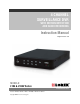
4 CHANNEL SURVEILLANCE DVR WITH MOTION DETECTION AND AUDIO RECORDING Instruction Manual English Version 3.0 MODELS: L104 & L104V Series www.lorexcctv.com Includes L104000, L104161, L104251, L104V000, L104V161 & L104V251 Copyright © 2007 Lorex Technology Inc.
Thank you for purchasing the 4 Channel Surveillance DVR (with Motion Detection and Audio Recording). Lorex is committed to providing our customers with a high quality, reliable security product. The L104 series offers excellent performance at a value price. This small form (9x12x2”) Surveillance DVR provides real time recording in quad mode, single channel audio recording and motion detection – scheduled – continuous mode recording. The L104 also has a remote controller and password protection.
Important Safeguards Important Safeguards In addition to the careful attention devoted to quality standards in the manufacture process of your video product, safety is a major factor in the design of every instrument. However, safety is your responsibility too. This sheet lists important information that will help to assure your enjoyment and proper use of the video product and accessory equipment. Please read them carefully before operating and using your video product. Installation 1.
Important Safeguards Service Use 13. Servicing - Do not attempt to service this video equipment yourself as opening or removing covers may expose you to dangerous voltage or other hazards. Refer all servicing to qualified service personnel. 19. Cleaning - Unplug the video product from the wall outlet before cleaning. Do not use liquid cleaners or aerosol cleaners. Use a damp cloth for cleaning. 14.
General Precautions General Precautions 1. All warnings and instructions of this manual should be followed 2. Remove the plug from the outlet before cleaning. Do not use liquid aerosol detergents. Use a water dampened cloth for cleaning 3. Do not use this unit in humid or wet places 4. Keep enough space around the unit for ventilation. Slots and openings in the storage cabinet should not be blocked 5.
L104 Series Features L104 Series Features • • • • • • • • • • • • Rugged Metal Cabinet Small (15.3” x 13.0” x 5.5” / 388mm x 338mm x 89mm) discrete size Easy set up and operation Real time viewing and recording Large capacity ‘Security Certified’ Hard Disk Drive (100% duty cycle) USB computer link and software for PC viewing, search and archiving Save video to the PC (Using the PC Viewer Software*) in *.MYS or *.
Table of Contents Table of Contents Getting Started .............................................................................................................................................. 8 L104 Series - Front ...................................................................................................................................8~9 L104 Series - Back......................................................................................................................................
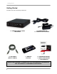
Getting Started Getting Started The DVR comes with the following components: 1 x COMPACT DIGITAL VIDEO RECORDER 1 x USB CABLE (MALE TO MALE) 1 x POWER ADAPTOR 1 x POWER ADAPTOR CABLE 1 x REMOTE CONTROL 1 x HARDWARE MANUAL 1 x QUICK START GUIDE 1 x SOFTWARE CD CHECK YOUR PACKAGE TO CONFIRM THAT YOU HAVE RECEIVED THE COMPLETE DVR, INCLUDING ALL COMPONENTS SHOWN ABOVE.
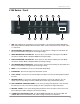
L104 Series - Front L104 Series - Front 1 2 3 4 5 8 9 10 11 6 7 12 1. USB - One USB 2.0 port is provided to connect the DVR to a PC using the provided USB (Male to Male) Cable and the included PC Viewer Software. Video can be archived on the PC in either *.MYS or *.AVI format. 2. UP NAVIGATION / CH1 DISPLAY - Press the key to view Channel 1 during Live View Mode. Use this key in Menu Mode to Navigate UP and change settings. 3.
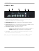
L104 Series - Back L104 Series - Back 1 2 3 4 5 1. VGA VIDEO OUTPUT (L104V SERIES ONLY) - Video Output port to connect the unit to a Computer Monitor. Directly reflects the current onscreen images. 2. BNC VIDEO OUT - Video Output port to connect the unit to a DVR or TV. Directly reflects the current onscreen images. 3. BNC VIDEO INPUTS - Channel 1~4 camera inputs (used to connect Cameras with BNC connection type). Cameras with BNC connections require an additional power adapter. 4.
Remote Control Remote Control Listed below is a quick reference for the Remote Control. All Buttons described above function the same as the Front Panel buttons. CHANNEL BUTTONS 1~4 - Press to select a specific camera by number. The Number Buttons are also used to input the DVR Password. NAVIGATION - Navigates UP and DOWN in MENU and SEARCH modes. REVERSE / MUTE – - Press to Reverse the Playback of previously recorded Video (In Playback Mode).
Camera Installation Camera Installation Before you install the camera*, carefully plan where and how it will be positioned, and where you will route the cable that connects the camera to the DVR. Installation Warnings: • • • • • Select a location for the camera that provides a clear view of the area you want to monitor, which is free from dust, and is not in line-of-sight to a strong light source or direct sunlight.
Connecting BNC Cameras Connecting BNC Cameras 1. Connect the 60ft Extension cable to the Camera and DVR: A. Connect the Barrel Power connector to a power adaptor. B. Connect the BNC connector to an available BNC Port (CAM 1~4) on the DVR. C. Connect the Male Power connector to the Camera. D. Connect the BNC connector to the Camera. Connect to DVR and Power Adaptor 2. Connect the Power Adaptor to a wall outlet.
Display Modes Display Modes Initial Loading Sequence The unit will automatically begin loading when power is connected to the DVR. 1 1. The DVR will perform a Firmware check. During the loading sequence, the version of Hardware and Mode (NTSC or PAL) will be displayed. 2. Once the Firmware check is completed, the DVR will check the Hard Drive. If a new drive has been installed, the system will prompt to format the new drive. 3.
Display Modes General Display Overview 1. DATE & TIME - Displays the current Date and Time for the DVR. 2. PASSWORD INPUT - The Password Input appears when manually stopping the Recording, or entering Menu Mode. The default password is 111111. 3. CAMERA TITLE & RECORDING STATUS - Displays the Camera Name (Up to 8 Characters) and Displays the current Recording Status (if the System is recording the □ symbol appears). 4. V-LOSS MESSAGE - Appears when the Camera is not sending a Video Image.
System Setup Controls System Setup Controls • Enter the MENU screen by pressing the MENU button ( ). Enter the password to display the Menu Selection Screen. The Default password is <111111> - press MENU to accept the password. • Scroll through the 7 options by pressing the UP & DOWN (▲▼) buttons on the Front Panel or Remote Control. • To enter a sub-menu, navigate to the option and press the RIGHT button (►). To exit a SUBMENU, press the MENU button.
System Setup Controls System Menu Tree MAIN MENU SYSTEM SETUP BUZZER ALARM TIME VIDEO LOSS ALARM AUDIO RECORD AUDIO MUTE AUDIO INPUT VOLUME AUDIO OUTPUT VOLUME PASSWORD SETUP TIME SETUP CAMERA SETUP CAMERA: CH1~CH4 LIVE ON/OFF RECORD ON/OFF BRIGHT SETUP CONTRAST SETUP COLORS SETUP AUTO SWITCHING RECORD SETUP RECORD QUALITY VIDEO QUALITY RECORD FRAME RATE 17
System Menu MAIN MENU RECORD SCHEDULE MOTION SETUP HARD DRIVE SETUP OVERWRITE ENABLED MASTER HDD SIZE MASTER HDD USED MASTER HDD FORMAT XVGA RESOLUTION (L104V Series ONLY) SYSTEM RESTORE System Menu The options in the System Menu control the settings for the DVR. • • • • • • • • BUZZER ALARM TIME: Sets the length of time that the Alarm Buzzer will sound for (i.e. Video Loss Alarm Buzzer, Restart of System Alarm Buzzer etc.). The setting for the Alarm Buzzer ranges from 0 (off) ~ 30 Seconds.
System Menu Camera Setup Menu The Camera Menu allows the settings to be changed for each of the 4 cameras. • • • • • • • CAMERA: Switch between CH1, CH2, CH3 and CH4 to adjust the settings for each camera. LIVE ON / OFF: Turns the Live Camera View to ON / OFF. The camera will continue to record regardless of the Onscreen Display. RECORD ON / OFF: Turns the recording for the Camera to ON or OFF. BRIGHT SETUP: Changes the Brightness of the camera.
System Menu Record Schedule Menu The Record Schedule controls the Recording Type per hour for 24 hours (full day) for both Individual Camera and QUAD recording types. The Available Recording Types include: • • • T : Continuous (Schedule*) Recording (The DVR is constantly recording on all channels, based on individual camera settings). M : Motion Recording (The DVR only records when Motion is detected).
System Menu Hard Drive Setup Menu (cont.) • MASTER HDD FORMAT: Formats the DVR Hard Drive. Enter the System Password to format, or press the Menu Button ( ) to cancel the format. ENTER PASSWORD: ------ NOTE: Formatting the Hard Drive removes all accessibility to the Video Data on the Hard Drive (when using the DVR Search functions); however the data is still available through the PC Viewer (until overwritten).
Playback Controls Playback Controls • Press the PLAY/PAUSE (►/ ||) button when in Live View Mode will put the DVR into Playback Mode, playing the most recent event. • To search for a previous event, press the MENU Button ( ) when in Playback Mode. Pressing the MENU button will open the PLAYBACK EVENT SEARCH MODE window. > 1. DATE & TIME: Displays the Start and End Date/Time range. Use the Arrow Buttons (◄▲▼►) to change the dates. 2. EVENT LIST: Displays a listing of Events.
DVR PC Viewer Software DVR PC Viewer Software The PC Viewer software (included with the DVR) allows the Video Data from the DVR to be viewed using a USB link to a PC. Video saved to the PC Hard Drive (from the DVR) is written as a *.MYS file format, and can only be read using the PC Viewer Software. System Requirements: Supported Operating System PC Hardware & Software Windows 2000 (SP4) or Windows XP (SP2 or higher) Pentium 1.0 GHz; 512 MB RAM; DirectX 7.
PC Viewer – Main Window PC Viewer – Main Window 1 2 3 4 5 6 7 8 9 10 11 12 13 1. PC VIEWER MENU CONTROLS – The Menu Controls function in the same way as the GUI Controls on the Viewer Window: • Function Selector: Controls the onscreen location of the program and closes the application. • PC Viewer: Playback controls (Play, Pause, Fast Forward & Reverse). • Channel: Controls the onscreen video display (Single Channels, 2-Channel View & Quad View).
PC Viewer – Main Window (cont …) PC Viewer – Main Window (cont …) 3. CHANNEL TITLE & DATE – Displays the Channel Description (CH1 ~ CH4), and the Date and Time of the Recorded Video. 4. MYS PLAYER BUTTON 5. STREAM SELECT BUTTON - Launches the MYS Player Window (see below). – Used to select another Stream Device (disabled). 6. DVR STORAGE DEVICE INFORMATION – Displays details about the DVR including the Connection Type, Device Type, Storage Size and Length of Video (Stream in MB). 7.
PC Viewer – Main Window (cont …) – Saves the current video stream as an AVI file (AVI 10. CAPTURE VIDEO IN AVI FORMAT Files can be played back in a Video Playback application such as Windows Media Player®, as long as the correct Codecs are installed on the PC). • • • • • Load the Video into the Player Window. Use the Viewer Controls to locate the point in the video to start the Video Save. Press the PAUSE button on the Viewer Controls Press the Capture AVI Stream button.
Using the MYS Player Using the MYS Player When the MYS Player opens, an ‘Open File’ dialogue box appears. Select the MYS File to play back in the Viewer, and press the Open button.
MYS Player – Main Window (cont …) MYS Player – Main Window (cont …) 1. MYS PLAYER MENU CONTROLS – The Menu Controls operate in the same way as the PC Viewer Controls (see above). 2. VIDEO DISPLAY – Displays the Video in Single, 2-Channel or Quad View. The video is displayed in Quad view when the application loads. 3. CHANNEL TITLE & DATE – Displays the Channel Description (CH1 ~ CH4), and the Date and Time of the Recorded Video. 4.
DVR Specifications - Appendix #1 DVR Specifications - Appendix #1 Display Frame Rate Recording Frame Rate (QUAD Mode) Recording Frame Rate (Single Mode) Recording Modes Resolution Display Resolution Recording MJPEG Compression Format Audio Function HDD Capacity Backup Device Search Mode System Recovery Features & Functions Video Input Video Output VGA Output (L104V Series) Audio Input Audio Output Power (AC input) Dimensions (W x H x D) Weight Dimensions with Package (W x D x H) Weight with Package Oper
Full Connectivity Diagram – Appendix #2 Full Connectivity Diagram – Appendix #2 The following diagram outlines a general set of connections available with the DVR.
Hard Drive Replacement - Appendix #3 Hard Drive Replacement - Appendix #3 The DVR comes with a pre-installed Hard Drive; however the unit will work with a replacement single IDE Hard Drive (up to 500GB). NOTE: Make sure that the DVR is OFF and the power cable has been disconnected before changing the Hard Drive. Removing the Back Cover and Installed Drive 1. Remove the seven (7) screws from the DVR Cover. Remove the cover panel. 2. Remove all cables from the previously installed drive. 3.
Hard Drive Replacement (cont …) Hard Drive Replacement (cont …) Installing the New Drive • • • Place the new drive in the case, and reattach the holding screws. Reconnect the cables in the same way as connected to the previous drive. o Reconnect the IDE Cable. Confirm that the cable is securely connected within the DVR and to the Hard Drive. o Reconnect the Hard Drive power cable. Confirm the cable is securely connected to the Hard Drive.
Troubleshooting – Appendix #4 Troubleshooting – Appendix #4 When a malfunction occurs, it may not be serious and can be corrected easily. The following describes the most common problems and solutions. Please refer to the following before calling Lorex Technical Support: Problem: DVR Unit is not receiving power, or is not powering up Check: • Confirm that all cables are connected correctly. • Confirm that the power adapter is securely connected to the back of the unit.
Troubleshooting (cont…) Troubleshooting (cont…) Problem: The picture on the DVR is poor, shrinks or flickers Check: • Check the camera video cable and connections • Disconnect and reconnect the cable at the DVR and at the Camera • Clean the camera lens • Adjust the CONTRAST and BRIGHTNESS settings in the Menu • Check that the Camera is not in direct sunlight Problem: There is no picture appearing on a Channel / Camera is not displaying Check: • Check the camera video cable and connections • Disconnect and
Recording Charts (NTSC / PAL) - Appendix #5 Recording Charts (NTSC / PAL) - Appendix #5 The following charts are based on an 80GB Hard Drive (using 4 Cameras) and provide an approximation of hours based on the Quality and Frame Rate. The charts are provided for reference only, as actual recorded data may vary in size.
Optional Accessories Optional Accessories The following accessories are available to add to your existing DVR BNC DOME TYPE CAMERAS BNC CAMERAS CAMERA EXTENSION CABLES NIGHT VISION ACCESSORIES CAMERA ADAPTOR CABLES To order these accessory items, or for a complete listing of available products, please visit us on the web at: WWW.LOREXCCTV.
It’s all on the web Product Information Specification Sheets User Manuals Software Upgrades Quick Start Guides Firmware Upgrades VISIT www.lorexcctv.com www.lorexcctv.com Lorex Technology Inc.