4-CHANNEL NETWORK TRIPLEX DIGITAL VIDEO RECORDER with VGA Output Instruction Manual English Version1.0 MODEL: DXR43000 Series 4 Channel Network DVR www.lorexcctv.com Copyright © 2005 Strategic Vista International Inc.
The DVR converts analog video into digital format and records them on a removable hard disk drive. Digital video allows you to quickly access and search for a specific time segment or event which has been recorded. This system features three different quality settings providing recording capability depending on your hard drive unit. To learn more about this system or to find out more about our products available, please visit our website at : www.lorexcctv.com CAUTION RISK OF ELECTRIC SHOCK. DO NOT OPEN.
NOTE This equipment has been certified and found to comply with the limits regulated by FCC, EMC and LVD. Therefore, it is designed to provide reasonable protection against interference and will not cause interference with other appliance usage. However, it is imperative that user follows this manual’s guidelines to avoid improper usage which may result in damage to the unit, electrical shock and fire hazard or injury.
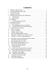
CONTENTS 1 2 3 4 5 GENERAL PRECAUTIONS ...................................................................................... 1 CAUTIONS AND DVR FEATURES .......................................................................... 3 SYSTEM INCLUDES: ............................................................................................... 5 GETTING STARTED................................................................................................. 6 DESCRIPTION OF PARTS AND FUNCTIONS ...............
1 GENERAL PRECAUTIONS Read Instructions All of the safety and operating instructions should be read and understood before the product is used. Retain Instructions The safety and operating instructions should be retained for future reference. Heed Warnings All warnings on the product and the instruction manual should be followed. Follow Instructions All operating and usage instructions should be followed for optimal performance Cleaning Disconnect this video product from the power supply before cleaning.
Overloading To avoid the risk of fire and electric shock, do not plug this product into an over- loaded power supply. Object and Liquid Entry Never push objects into the openings of this product as they may touch dangerous voltage points that may result in fire or electric shock. Never spill a liquid of any kind on this product. Servicing Do not attempt to service this product yourself as opening or removing covers may expose you to voltage or other hazards.
Power Lines An outside antenna system should not be located in the vicinity of overhead power lines or other electric light or power circuits, or where it can fall into such power lines or circuits. When installing an outside antenna system, extreme care should be taken to keep from touching such power lines or circuits as contact with them might be fatal. Wall or Ceiling Mounting The product should be mounted to a wall or ceiling only as recommended by the manufacturer.
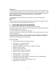
• • • • • • • • • • • Recording Speed: 60 fields/sec Security password protection On Screen Display and Real Time Clock Function Remote Control as well as Main Panel operation Supports 20 ~300 GB HDD Quick Multiple Search capability Viewing options: Quad, Sequential, PIP, Full Screen Supports Pan/Tilt control (Pelco D Protocol): Channel 1 only.
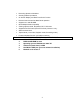
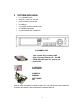
3 SYSTEM INCLUDES: • • • • • • • (1) 4 CHANNEL DVR Optional (1) HDD, 20~300 GB (2) KEYS FOR CARTRIDGE (4) CABLES (1) POWER ADAPTER AND CORD (1) OWNER’S MANUAL (1) NETVIEWER SOFTWARE CD 4 CHANNEL DVR Your system may include a HDD with a capacity between 20 ~ 300 GB (HDD) depending on the system you purchased. 2 KEYS FOR CARTRIDGE OWNER’S MANUAL SOFTWARE CD CHECK YOUR PACKAGE TO MAKE SURE THAT YOU RECEIVED THE COMPLETE SYSTEM, INCLUDING THE COMPONENTS SHOWN ABOVE.
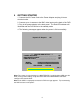
4 GETTING STARTED 1. Connect the AC Power Cord to the Power Adapter and plug it into an electrical outlet. 2. Connect up to 4 cameras to the BNC video inputs on the back of the DVR. 3. Plug in the power adapter to the back panel. The Red LED indicator will illuminate and the DVR will be in the standby mode 4. The following messages appear when the power is ON successfully.
*** NETWORK INFOMATION *** MAC ADDRESS : XX XX XX XX XX XX IP ADDRESS : 192 . 168 . 001 . 150 SUBNET MASK : 255 . 255 . 255 . 000 GATEWAY : 192 . 168 . 001 . 001 PORT : 5000 Note: The above message indicates the network values set in the DVR. Note: The settings for the network values can be changed in the MAIN MENU SETTINGS.
5 DESCRIPTION OF PARTS AND FUNCTIONS 5.
5.1.1 CABINET FOR CARTRIDGE CASING The cabinet is located on the front panel behind a panel which flips forward to reveal the removable cartridge casing (contains the HDD). KEYHOLE LED LIGHTS HANDLE KEYHOLE Insert the key into the keyhole and turn to lock or unlock the cabinet. LED Indicator Lights Indicator lights for the power and the HDD access HANDLE Lift the handle and pull to slide the Cartridge Casing out of the DVR. 5.1.
1. ARROW/CHANNEL BUTTONS (eCH1, dCH2,cCH3,fCH4) These buttons perform the following functions: a) Displays a picture in Full Screen In Quad 1 mode: Select the Channel 1 button and hold it for 2-3 seconds to view Camera 1 in Full Screen. To view the other camera locations, press CH2, CH3, and CH4 buttons. b) Freezes a specific camera.
5. PIP / COPY BUTTON (Picture in Picture) NOTE The PIP function is only accessible by the remote control. The PIP Button allows you to view two camera locations simultaneously, one being the main channel, the other being viewed as a sub-picture. Dual PIP can also be selected, which displays two sub-pictures as illustrated below. To change between Single PIP and Dual PIP, repeatedly press the PIP button.
6. SEARCH / EVENT BUTTON a) SEARCH: Pressing this button brings up the Search menu, which allows you to quickly find recordings. b) EVENT: Pressing this button brings up a list of up to 3000 Events, including Power, Loss and Alarms. You can scroll through Events using the ▲ and ▼ keys, and navigate between Pages of Events using the ◄ and ► keys. Press the QUAD / ENTER Button to exit the Event list.
TIMER: The LED will be ON when the schedule recording is set (i.e. when you set up the DVR to record automatically in SCHEDULE REC SET, see THE MAIN MENU SETTINGS, page 19). ALARM: LED will be ON when the ALARM or MOTION function is set to ON. When the ALARM or MOTION function is ON, the LED will blink as an Alarm is being triggered. HDD FULL: If the OVERWRITE menu is set up, the LED will not blink in any case.
5.1.
5.2 BACK PANEL (DESCRIPTION OF PARTS AND FUNCTION continued) RS-232 VGA OUT VIDEO IN VIDEO OUT AUDIO IN / OUT 1. VIDEO IN Channel 1-4 camera video input BNC port. 2. VIDEO OUT Composite Output for connecting to another Monitor or VCR. 3. AUDIO IN / OUT. Audio input / output through line 4. ETHERNET. Available to view live and recorded data on the HDD through the Internet or a LAN 5. VGA OUT. Output for connecting to a Computer Monitor 6. RS-232.
To DC-12V power source RS-485 (–) ALARM IN RS-485 (+) COM ALARM OUT SLAVE IDE 1. ALARM IN These terminals are used to connect external motion sensors, door / window contacts, etc. 2. COM 3. ALARM OUT Send a signal to a VCR or other devices in an Alarm or motion situation. 4. RS - 485 ( +, –) Connect the PTZ control wires to these terminals 5. SLAVE IDE Output for connecting to a Slave Monitor or VCR. 6.
6 MAIN MENU From the main menu controls, the user accesses each sub-menu to change its properties.
HDD INFO DISP RS232 BAUD PASSWORD SET NETWORK(TCP/IP) USER GUEST IP ADDR SUB NET GATEWAY PORT SYSTEM (Ⅱ) HDD / REC SET REC QUALITY REC REC SPEED REC SELECT HDD CLEAR ALL HDD OVERWRITE HDD SLAVE ALARM REC SET ALARM REC PRE ALARM REC REC QUALITY REC SPEED REC DURATION SCHEDULE REC SCHEDULE REC REC SETTTING FIRMWARE UPGRADE EXIT 18 FIRMWARE UPGRADE
6.1 THE MAIN MENU SETTINGS Enter the MENU screen by pressing the Setup button. Scroll through the 11 options by pressing the UP and DOWN buttons (i.e. ◄=left, ▲=up, ▼=down, or ►=right). To enter a sub-menu, press the Enter button (i.e. QUAD/ENTER) where the highlighted scroll bar is located. To exit the Main Menu, scroll down to the Exit option and press the Enter button. Note: In sub-menu of the Main Menu, you can exit the Menu mode by selecting Exit, or you can return to the Main Menu by selecting Return.
(i) ALARM: Selecting [OFF] disables PIR motion detection from triggering any alarm. Selecting [OSD] will allow alarms to be triggered, and the letters “AL” ill appear on the screen of the camera location where the alarm is taking place. A third option, [OSD+BUZZER] will both display “AL” and emit a buzzer sound in the event of an alarm. (ii) CH 1-4: Set the length of alarm time for each channel between 1~59 seconds. Additionally, you can select the Alarm Input. The default setting is N/O (Normally Open.
01 02 00 05 03 04 SYSTEM SET ( l ) -This sub-menu allows you to configure various preferences on the system, related to Monitor settings. 6. (i) KEY BUZZER : When set to [Y], the system will make a sound when a key is pressed on the remote control or on the main panel of the monitor. (ii) LOSS BUZZER : When set to [Y], the system will make a sound when a camera becomes disconnected. (iii) QUAD LINE : Activates and deactivates the border line in Quad mode.
data transmission, can be set to OFF, 2400, 4800, 9600, or 19200. (iii) PASSWORD SET : If you select [Y], you will need to input a password when you enter the Main Menu. Use to change your password for accessing the Menu. The password must be 4 digits. The default Password is “0000”. Selecting [N] will allow you into the menu without a password. NOTE NETWORK CONFIGURATION (Part of SYSTEM SET (ll)) (iv) NETWORK (TCP/IP): The User can set the network for OFF, DYNAMIC IP or STATIC IP.
(i) REC QUALITY : Sets the quality level of recording. Available settings are: Low, Basic, Normal, High and Best. Note: Higher quality recording consumes more memory on your HDD. (ii) REC RESOLUTION (iii) REC SPEED: Allows you to set the Images Per Second for recording. Available IPS settings are: 1, 2, 3, 5, 10, 15, 30 & 60. The speed of 60 IPS is also known as “Real Time”. The slowest Time Lapse speed is 1 IPS; it will allow for the longest recording durations but it records less information.
NOTE 9. After activating the Slave HDD, you need to restart your system by turning the Main Power Switch (located on the back of the monitor) OFF and then ON again in order for the system to recognize the Slave HDD. ALARM REC SET - This sub-menu allows you to configure the Recording parameters under the Alarm condition. (i) ALARM REC: This setting selects whether or not the DVR will record automatically when a Motion Detection or a PIR alarm is triggered.
this will result in a loss in recorded activity and the schedule may be ignored. To delete a scheduled recording, place the cursor on the selected time and press the ◀, ▶ key. “CURRENT LINE DELETE? [Y] / [N]” is then displayed. If [Y] is selected, the selected schedule is deleted. 11. FIRMWARE UPGRADE : Used to upgrade most recent Firmware. Once you choose this menu, the system will ask you once again whether you will be proceeding with the Upgrade process.
7 PB SET/REC HDD SET The DVR allows you to easily find sections of recorded video using the Search feature. Press the SEARCH button to access the “PLAYBACK SEARCH SET” menu. [ PLAYBACK SEARCH SET ] PB:[ MASTER ] REC:[ MASTER ] 1. 2. 3. 4. 5. LAST RECORD FULL LIST ALARM LIST TIME SEARCH EXIT (1) LAST RECORD : Plays the most recent recording. (2) FULL LIST : Shows a listing of all recorded video on the HDD, sorted by time. (3) ALARM LIST : Shows a listing of all recorded video triggered by an Alarm.
8 PLAYBACK OPTION When the PLAY button is pressed, one of the Playback Search menus will appear. The Playback menu that appears upon pressing PLAY depends on the Search option that was last used. For example, if the last Search option used was a Time Search, then pressing PLAY will bring up the Playback Time Search. If the last Search option utilized was a Last Record, then pressing play will simply play the most recent recording. 8.
10 PAN / TILT ZOOM : The DVR is equipped with a built-in Pan/Tilt Zoom feature, which is only available when used in conjunction with a compatible Pan/Tilt Dome camera. The Pan/Tilt Zoom feature supports “Pelco D” protocol, and RS-485 Port. To access and operate the PTZ feature, follow these instructions: 1. Connect a compatible Pan/Tilt Zoom Dome camera to RS-485 Port; 2. Go to the SYSTEM sub-menu and set the PAN/TILT(CH1) option to “Y”; 3.
11 REMOTE CONTROL Features of the Remote Control. For more details on specific remote control features, refer to the Front Panel features. KEY MENU 1-4 FRZ 1 FRZ 2 FRZ 3 FRZ 4 PAN / TILT AUDIO SEL FUNCTION DESCRIPTION SLEEP Mode On/Off. Brings up the Main Menu. Allows user to select individual cameras. Freezes the Channel 1 screen. Freezes the Channel 2 screen. Freezes the Channel 3 screen. Freezes the Channel 4 screen. Enters Pan/Tilt Zoom mode. REC STOP REC ▲,▼ UP / DOWN arrow keys, used in Menu mode.
12 CAMERA INSTALLATION Connect the camera to the CAMERA INPUT on the rear panel of the system.
14 MONITOR & STANDARD VCR/ INSTALLATION Connect the a VCR and a monitor to the inputs on the rear panel of the system. VIDEO INPUT AUDIO INPUT VIDEO INPUT AUDIO INPUT VCR MONITOR CONNECTION TO A MONITOR FOR VIEWING You can connect your DVR to a monitor for viewing purposes and for On Screen display set-up. Connect a BNC video cable, RCA audio cable from your DVR marked “VIDEO OUT / AUDIO OUT” to the audio/video input on the monitor.
15 CONNECT A TYPICAL LOREX MONITOR CONNECTION OF A TYPICAL LOREX OBSERVATION MONITOR TO A DXR43000 BACK OF LOREX OBSERVATION MONITOR BNC (Input/Output) BNC video input DXR43000 DVR NOTE: On Lorex quad monitors the BNC video input channel connectors also support video output. The BNC video input/output on a Lorex quad monitor can be connected to BNC video input of the DVR. To view the menu or playback of the DVR, press the monitor’s VCR button located on the front of the monitor.
16 NETWORK, ALARM & COMPUTER INSTALLATION INTERNET SENSOR REAR COMPUTER 232 PORT 33
17 NETWORK IMAGE SIZE & SPEED 720 X 240 LOW BASIC NORMAL HIGH BEST IMAGE SIZE 14K ~ 15K 16K ~ 17K 19K ~ 20K 23K ~ 24K 32K ~ 33K IPS 13 ~ 18 10 ~ 15 09 ~ 14 09 ~ 14 09 ~ 14 360 X 240 IMAGE SIZE 08K ~ 09K 10K ~ 11K 11K ~ 12K 14K ~ 15K 19K ~ 20K IPS 25 ~ 30 23 ~ 28 23 ~ 28 15 ~ 20 10 ~ 15 The demand on the volume of the HDD can be different depending on the displayed picture.
18 RECORDING TIME (IN HOURS) 01 IPS 02 IPS 03 IPS 05 IPS 10 IPS 15 IPS 30 IPS 60 IPS 01 IPS 02 IPS 03 IPS 05 IPS 10 IPS 15 IPS 30 IPS 60 IPS LOW BASIC NORMAL 720 X 240 HIGH 1569Hours 777Hours 519Hours 311Hours 156Hours 104Hours 52Hours 26Hours 1429Hours 714Hours 473Hours 286Hours 142Hours 95Hours 47Hours 24Hours 1250Hours 625Hours 417Hours 249Hours 125Hours 83Hours 42Hours 21Hours 1026Hours 513Hours 343Hours 206Hours 103Hours 68Hours 34Hours 17Hours LOW BASIC 360 X 240 NORMAL 2581Hours 1290Hou
19 RECORDING TIME (Gigabytes per hour) 01 IPS 02 IPS 03 IPS 05 IPS 10 IPS 15 IPS 30 IPS 60 IPS 01 IPS 02 IPS 03 IPS 05 IPS 10 IPS 15 IPS 30 IPS 60 IPS LOW 0.051GB/H 0.103GB/H 0.154GB/H 0.257GB/H 0.514GB/H 0.77GB/H 1.54GB/H 3.08GB/H LOW 0.031GB/H 0.062GB/H 0.093GB/H 0.155GB/H 0.309GB/H 0.464GB/H 0.928GB/H 1.86GB/H BASIC 0.056GB/H 0.112GB/H 0.169GB/H 0.28GB/H 0.562GB/H 0.843GB/H 1.69GB/H 3.37GB/H 720 X 240 NORMAL 0.064GB/H 0.128GB/H 0.192GB/H 0.321GB/H 0.642GB/H 0.962GB/H 1.92GB/H 3.85GB/H HIGH 0.
20 INSTALLING THE MASTER HDD The HDD serves the same purpose in a DVR as a video cassette does in a VCR. However, installing the HDD is a bit more complicated. Please follow the next steps carefully in order to ensure proper installation. The compartment located on the front panel of the DVR is the removable Cartridge Casing in which you insert the HDD. The various parts of the Cartridge Casing are labeled for your reference. 1. Remove the Cartridge Casing from the DVR Lift the Handle and pull towards you.
The 4 Pin connection is the DC Power cable, and the wider cable is the standard Hard Drive IDE type connection. 4. Secure the HDD in the Casing Use screws and tighten them, positioning the HDD into place. 5. Slide the top Cover over the Cartridge Casing Slide the Cover forward over the Cartridge Case. Ensure it is secured in place over the release latch. 6. Reinsert the Cartridge Casing into the DVR Fully insert the Cartridge Case into the DVR.
7. Lock the Cabinet Lock the cabinet by turning the key clockwise. A (locked) B (unlocked) If you need to unlock the cabinet, turn the key counter-clockwise from the position shown above. IF YOU DO NOT LOCK THE CABINET, THE DVR SYSTEM WILL NOT FUNCTION PROPERLY.
21 THE NETVIEWER SOFTWARE This section provides instructions for installing and using the NetViewer, which is included with the DXR 43000 series DVR. The minimum requirements for this installation are as follows: • CPU: SPEED SHOULD BE 1.0GHZ or more • RAM: 256 MB RAM or more • Operating System: Windows 98/ 2000/ XP • Video card (stand alone): 32 MB • Hard Disk:10 MB (free space for software installation) • Network card: 10 base T 21.
21.2 INSTALLING THE NETVIEWER IN YOUR PC Follow these steps to install the NetViewer from the supported CD-R. 1. Exit all applications currently running in the selected PC. 2. Insert the supplied software CD in the CD-ROM drive. 3. Locate the Setup icon on your CD and double click on setup icon Figure 1: Startup Screen 4. Press Next Figure 2: Customer Information 41 .
5. Enter your name and organization and press Next. Figure 3: Destination Folder 6. Enter the desired folder for the installation or press Next.
7. Press Install to start installing the program. Figure 5: Installation Complete 8. Press the Finish button to end the installation process. 9. Open the NetViewer icon located on your desktop and click on it. 10. The Netviewer main window will appear on the screen as shown below. 21.2.
22 SETUP CAMERA FOR REMOTE VIEWING See the following instructions to setup the camera for remote viewing over the internet: 1. 2. 22.1 NETWORK CONFIGURATION SETTINGS (Page 44) VIEWING THE CAMERAS (Page 45) NETWORK CONFIGURATION SETTINGS PROCEDURE Click on the Setup icon , a small setup window will appear. Enter the DVR IP address (i.e. 192.168.1.5) Enter the DVR Port (i.e. 5000) Set the User ID (i.e. admin, Max. 5 digit) Set the video format (NTSC/PAL).
22.2 VIEWING THE CAMERAS PROCEDURE Press the connect icon to start viewing the cameras. If the setup is properly done, the cameras will appear on the screen (see Figure 6,page 45). Figure 6: Remote Camera Views NOTE If you are behind a router you need to open 4 ports related to the main port. Example: If you set up port 5000 you need to open ports 5000, 5001, 5002 and 5003 in order to get connected remotely.
22.3 22.3.1 NETWORK CONFIGURATION NETVIEWER PANEL DESCRIPTION 12 13 11 10 9a 8a 2 1 3 4 5 6 9b 8b 7 1. Used to “PLAY, STOP, PAUSE, REW and FF” the recordings saved on the HDD of the DVR. When the PLAY button is pressed the most recent recorded data will be played regardless of search data set on the DVR. 2. Select the display mode. Available modes are QUAD, FULL, PIP, POP. You could change the channel right button of the mouse on each mode. 3. Change the NETVIEWER image screen to Full Screen Mode.
5. Set the Contrast/Bright/Sharpness/Color of each channel. Choose the channel. Set the Brightness Value. Set the Contrast Value. Set the Hue Value. Set the Saturation Value. 6. TIME SEARCH. This feature allows you to Search events on your DVR. Press the Search button. Select the desire date and time and press the Search button. The DVR will start searching the data. If the data were found, it will be played automatically.
22.3.2 AVI SAVING METHOD PROCEDURE Start the NETVIEWER application and press the SETUP BUTTON The SETUP window will come out (see Figure 7). . Figure 7: Netviewer Setup Window From the SETUP menu, select the REC menu and the window will appear. The REC menu is used to set the values to save the images displayed on the Viewer. Note: If you choose the Encoding Codec, you can select the relevant Codec you want to use. You could use any Codec out of the preinstalled Codec on your computer.
22.3.3 CODEC SETTING PROCEDURE 4 1 2 3 Figure 8: Codec Setting 1. Choosing a Codec window displays the currently available Codec on your computer. Choose the Codec you want to use. 2. Select the image size to be saved. 3. Set the IPS value to be saved. For example: You could set a new IPS value to be ¼ the IPS value displayed on #4. If #4 displays the IPS = 16, you could set the new value at #3 IPS = 4 (i.e. ¼ x 16 IPS = 4 IPS). 22.3.4 RECORDING DIRECTORY SETTING 1. Choose the Folder to be saved.
Note: With the available DVR format, you can only playback with the Local Viewer. AVI format can be played with the Windows Media player or other player. 22.3.6 RECORDING CHANNEL SETTING 1. Select the Channels to be saved. Recording LOCAL REC BUTTON (records to the hard drive of your local computer) 2. Press the LOCAL REC BUTTON to start recording. Press the LOCAL REC BUTTON again to stop recording.
22.3.7 ADMIN USER ID (OR GUEST) PASSWORD CHANGE PROCEDURE Click on the Setup icon to open the setup window. Note: you must be connected to the DVR to change the password Click on the admin icon • • • • • Enter the current password Enter the ID of the admin user (Max. 5digits) Enter new the password for the admin user Verify the new password of the admin user. Click OK to finish The change password message window will appear .
22.3.8 REMOTE CAPTURE VIDEO SETTINGS This menu allows you to configure the video capture settings to save and capture the video of the DVR on your PC. Click on the Setup icon and select the REC tab. Set the video compress Codec. Select the folder to save the video. Set the video format to be saved Select the channel to be saved. Press OK to finish. 22.3.9 REMOTE DVR SETTINGS This menu allows you to configure some DVR settings from a remote location. Click on the Setup icon and select the DVR tab.
Show the HDD information installed on the DVR. The value is the physical capacity of each HDD, and the value in the parenthesis is the available capacity for saving. Select the HDD for Recording Select the HDD for Playback Press button to apply the changes. 60 IPS is equal to 30 frames per second. 1 IPS is equal to 0.5 frames per second. The demand on the volume of HDD can be different depending on the displayed picture. Set the priority level to High for the best possible program performance.
23 TECHNICAL SPECIFICATIONS DVR Recording Speed : HDD Capacity : Recording Video Quality : Recording Mode : Playback Mode : Video Display Mode : Video Input : Audio Input : Video Output : Audio Output : Alarm In/Out : Compression Rate : View Resolution : Record Resolution : Display Frame : Recording Frame : OS : Power Consumption : Power Input : Operating Temperature : Storage Temperature : Weight : Dimensions : 60 Fields / Sec. 300GB(Max.
24 TROUBLE SHOOTING If the system does not function properly, please check the following points. PROBLEM DVR SOLUTION Slave HDD not readable Check the jumper PIN connection. Activate the Slave HDD in the Menu option HDD SLAVE.
25 CARE AND MAINTENANCE Please follow these instructions to ensure proper care and maintenance of this system Keep your monitor and camera dry. If it gets wet, wipe it dry immediately. Use and store your unit in normal temperature environment. Extreme temperatures can shorten the life of the electronic devices. Handle the monitor carefully. Dropping it can cause serious damage to the unit. Occasionally clean the unit with a damp cloth to keep it looking new.
It’s all on the web Product Information Specification Sheets User Manuals Software Upgrades Quick Start Guides Firmware Upgrades VISIT www.lorexcctv.com www.lorexcctv.com Strategic Vista International Inc.