067392-++2137438 45 ,-+/+. L400 SERIES NETWORKABLE DVR Instruction Manual English Version 1.0 MODEL: L404/L408/L416 www.lorexcctv.com Copyright ¤ 2006 LOREX Technology Inc.
067392-++2137438 45 ,-+/+. Thank you for purchasing the L400 Series DVR. Lorex is committed to providing our customers with a high quality, reliable security product. The L400 Series line of Pentaplex Network DVR’s offer a full-featured Networkable video recording solution. Record in Real Time with 120 fps recording capability. Images can be easily transferred using the built in CDRW optical drive or USB flash drive.
067392-++2137438 45 ,-+/+. Important Safeguards Important Safeguards In addition to the careful attention devoted to quality standards in the manufacture process of your video product, safety is a major factor in the design of every instrument. However, safety is your responsibility too. This sheet lists important information that will help to assure your enjoyment and proper use of the video product and accessory equipment. Please read them carefully before operating and using your video product.
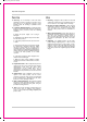
067392-++2137438 45 ,-+/+. Important Safeguards Service Use 13. Servicing - Do not attempt to service this video equipment yourself as opening or removing covers may expose you to dangerous voltage or other hazards. Refer all servicing to qualified service personnel. 19. Cleaning - Unplug the video product from the wall outlet before cleaning. Do not use liquid cleaners or aerosol cleaners. Use a damp cloth for cleaning. 14.
067392-++2137438 45 ,-+/+. General Precautions NOTE This equipment has been certified and found to comply with the limits regulated by FCC, EMC, and LVD. Therefore, it is designated to provide reasonable protection against interference and will not cause interference with other appliance usage.
067392-++2137438 45 ,-+/+.
067392-++2137438 45 ,-+/+. Table of Contents Table of Contents Getting Started .......................................................................................... 9 L400 Series - Front ................................................................................. 10 L400 Series - Back .................................................................................. 12 Remote Control ....................................................................................... 14 Starting the DVR .....
067392-++2137438 45 ,-+/+. Table of Contents Table of Contents Network Connectivity .............................................................................. 45 DVR Network Settings ............................................................................ 46 Finding Your External IP Address ............................................................................................. 46 Router Port Forwarding ...........................................................................
067392-++2137438 45 ,-+/+. Getting Started Getting Started The L400 Series comes with the following components: L400 SERIES DVR REMOTE CONTROL POWER CABLE CHECK YOUR PACKAGE TO CONFIRM THAT YOU HAVE RECEIVED THE COMPLETE SYSTEM, INCLUDING ALL COMPONENTS SHOWN ABOVE.
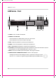
067392-++2137438 45 ,-+/+. L400 Series - Front L400 Series - Front 1 9 2 10 11 3 4 5 6 7 8 12 13 14 15 16 1. POWER - Turns the DVR unit ON/OFF. 2. NUMBER / LETTER PAD • Use the numbers to switch between cameras in View mode. • Use the Numbers and Letters for Menu data input. 3. STOP - Stops the playback of a previously recorded event. 4. PAUSE - Pauses the playback of a previously recorded event. 5. REV - REVERSES the playback of a previously recorded event. 6.
067392-++2137438 45 ,-+/+. L400 Series - Front 9 10 11 12 13 14 15 16 9. USB PORT - Connection port for a removable USB Hard Drive (USB Key) 10. OPTICAL DRIVE - Drive bay for (OPTIONAL) CD-RW Drive 11. IR RECEIVER - Used to receive a signal from a Remote Control 12. VOLUME UP - Raise system volume. 13. VOLUME DOWN - Lower system volume. 14. AUDIO - Switches between cameras 1-4 to receive audio * Only one channel audio available on the 4-Channel DVR Model. 15.
067392-++2137438 45 ,-+/+. L400 Series - Back L400 Series - Back 1 7 8 9 2 10 3 4 5 6 11 1. BNC VIDEO INPUTS - Video inputs for direct connection to Cameras or for looping input to a DVR. The number of ports will vary based on the DVR model (4 Channel, 8 Channel or 16 Channel). 2. RS232 PORT - Connection for an RS-232 Device * Not available on 4-Channel DVR Model. 3. ETHERNET PORT - Connects the DVR to a router for connection to the internet.
067392-++2137438 45 ,-+/+. L400 Series - Back 7 8 9 10 11 7. COMPOSITE - A Composite Video OUT connection used to connect the DVR to a Slave Monitor or DVR. 8. S-VIDEO - Outgoing connection for S-VIDEO 9. VGA PORT - Used to connect the DVR to a computer Monitor. * Not available on 4-Channel DVR Model. 10. AUDIO INPUTS - Connect up to 4 camera Audio inputs 11. AUDIO OUT - Connect the Audio OUT to the AUDIO IN on an DVR or Monitor.
067392-++2137438 45 ,-+/+. Remote Control Remote Control Listed below is a quick reference for the Remote Control. For details on specific features, refer to the L400 Series - Front Panel features on Pages 10-15 POWER BUTTON Turns the DVR ON NUMBER PAD Control for Cameras 1-16 & used for adding information in the Menu system. INFO Displays system details MUTE - Turns sound ON/OFF MENU - Accesses the DVR Menu System SEL / CONTROLS Switch between display modes (Single, Quad, 9 and 16).
067392-++2137438 45 ,-+/+. Starting the DVR - Self Test Screens Starting the DVR - Self Test Screens Once the DVR has been connected and powered on, the following self-test screens will appear: LOADING PROGRAMS ...... CHECKING HDD INTEGRITY ...... INITIALIZING DEVICES ... NOTE: If a new HARD DRIVE is detected by the system, the DVR will automatically FORMAT the new drive.
067392-++2137438 45 ,-+/+. Main Menu Control Main Menu Control • Enter the MENU screen by pressing the MENU button. The System Password may be required, based on system settings. • Scroll through the 5 Main options by pressing the KL buttons. • To enter a sub-menu, navigate to the option and press the SEL button. • To exit a SUBMENU, press the MENU button. To save the changes, select the SAVE & EXIT option and press the SEL button.
067392-++2137438 45 ,-+/+.
067392-++2137438 45 ,-+/+. Display Set Display Set This submenu allows you to change the DISPLAY options for the DVR unit and any connected cameras. Selecting options on this Menu will access additional settings and options.
067392-++2137438 45 ,-+/+. Display Set Display Set Camera Covert Turns Camera display ON/OFF The DVR unit will continue to record, even if all cameras are set to OFF. Camera Covert NOTE: The number of cameras displayed will change based on the Model of DVR - 4, 8 or 16 Cameras are available. Page: Camera 1: Camera 2: Camera 3: Camera 4: Save & Exit 1 OFF OFF OFF OFF 1. PAGE: Displays up to 8 camera configurations per page (second page only available for 16 camera setups).
067392-++2137438 45 ,-+/+. Display Set OSD ON/OFF Covert Turns the information display/camera names, hard drive usage, date and time) ON/OFF. OSD ON/OFF OSD: Save & Exit ON 1. OSD: Turns the ON SCREEN DISPLAY to ON/OFF. To change the setting, press the K and L buttons to highlight, and press the mo buttons to switch between ON/OFF. 2. SAVE & EXIT: Saves any changes made, and exits to the Main Menu. Press the K and L buttons to highlight, and press the SEL button to accept the changes.
067392-++2137438 45 ,-+/+. Display Set Set Display Sequence 1. FULL DISPLAY SEQUENCE: Set the length of time each camera is displayed in cycling Full Screen Display mode: • PAGE: Displays up to 8 camera configurations per page (second page only available for 16 camera setups). To change the page, press the K and L buttons to highlight, and press the SEL button to change to Page 2. • CAMERA 1 - CAMERA #: Set the length of time that a Camera is displayed in Sequence Mode.
067392-++2137438 45 ,-+/+. Recording Set Recording Set This submenu allows you to change the RECORDING options for the DVR unit. Selecting options on this Menu will access additional settings and options.
067392-++2137438 45 ,-+/+.
067392-++2137438 45 ,-+/+. Recording Set Recording Set Global Parameters Global Parameter Settings for General Parameters. Audio 1 Rec: OFF Audio 2 Rec: OFF Audio 3 Rec: OFF Audio 4 Rec: OFF Repeat Rec: ON Watermark Emb ON Rec Res 720 x 240 Save & Exit 1. AUDIO # REC: Turns Audio recording ON/OFF. press the K and L buttons to highlight, and press the mo buttons to change to ON/OFF. 2. REPEAT RECORDING: Allows the DVR unit to repeat recording.
067392-++2137438 45 ,-+/+. Recording Set Alarm Recording Alarm Settings for the DVR.
067392-++2137438 45 ,-+/+. Recording Set 3. SETUP ALARM: Configuration sub-menus for Alarm and Sensors. Press the K and L buttons to highlight, and press the SEL button to access the Alarm Submenu. Use the I and J to choose the cameras to be associated to each alarm: Alarm 1: Alarm 2: Alarm 3: Alarm 4: Setup Sensor Save & Exit 12 34 56 78 Page: 1: CH1: CH2: CH3: CH4: Save & Exit 4. SETUP SENSOR: Configuration for any Sensors attached to the Alarm block.
067392-++2137438 45 ,-+/+. Recording Set Motion Recording 1. CH1 - CH4: Lists all available cameras for configuration. Press the K and L buttons to highlight, and press the mo buttons to select the FPS or Quality for each CH. Use theK and L buttons to change the settings, and press SEL to accept the changes: • FPS: A set number of Frames Per Second (total) is divided between all available cameras based on Resolution settings.: • QUALITY: Set the quality level for the recording - High, Mid or Low. 2.
067392-++2137438 45 ,-+/+. Recording Set Schedule Recording Setup and configurations for Scheduled events. Schedule Recording CH/ FPS/ QUALITY CH1 8 HIGH CH2 8 MID CH3 8 LOW CH4 7 LOW Setup Schedule Save & Exit Schedule Setup Details NOTE: The number of cameras, alarms and sensors displayed on submenus will change based on the Model of DVR: 4, 8 or 16 Cameras are available. 1. CH1 - CH4: Lists all available cameras for configuration.
067392-++2137438 45 ,-+/+. Recording Set Recording ON/OFF Controls the Recording for Event Types. Recording ON/OFF Alarm Rec: Motion Rec: Schedule Rec: Save & Exit OFF OFF OFF ALARM RECORDING: Turns Alarm Recording ON/OFF. Press the K and L buttons to highlight, and press the mo buttons to switch between ON and OFF. MOTION RECORDING: Turns Motion Recording ON/OFF. Press the K and L buttons to highlight, and press the mo buttons to switch between ON and OFF.
067392-++2137438 45 ,-+/+. System Set System Set This submenu allows you to change the SYSTEM options for the DVR unit. Selecting options on this Menu will access additional settings and options.
067392-++2137438 45 ,-+/+. System Set System Set Basic Basic Settings for General Parameters. Language English Initialization Date Format MM-DD-YYYY Date/Time 01-15-2006 Information Save & Exit 1. LANGUAGE: Displays the current default language on the DVR (English). This option cannot be changed. 2. INITIALIZATION: Resets all settings to Factory Default. To change the setting, press the K and L buttons to highlight, and press the SEL button.
067392-++2137438 45 ,-+/+. System Set Disk Format Displays Hard Drive information. Disk Format Internal HDD NO External HDD NO Execute Format Save & Exit 1. INTERNAL HDD: Allows the user to format the HDD. Use the IJ to change this option to YES or NO. To format the Drive, set this option to YES and select the EXECUTE FORMAT option. 2. EXTERNAL HDD: Allows the user to format the External HDD. Use the IJ to change this option to YES or NO.
067392-++2137438 45 ,-+/+. System Set Client Account Configuration for additional user accounts. Client Account Add New Account Delete Account Save & Exit User ID Password Confirm Password Exit 1. ADD NEW ACCOUNT: Add a new user account to the system. Press the K and L buttons to highlight, and press the SEL button to access the User Setup screen: • USER ID: Enter the user ID. Press the KLIJ and Numbers (0-9) and Letters (A-Z, @ - _) on the front panel of the DVR to enter information.
067392-++2137438 45 ,-+/+. System Set PTZ Menu Pan / Tilt / Zoom control (for Pelco D or Pelco P Model Cameras only) PTZ (enter Password) Pan/Tilt/Zoom Focus Setup Save & Exit 1. PAN / TILT / ZOOM: Accesses the PTZ Control for a camera. Press the K and L buttons to highlight, and press the SEL button to access PTZ controls: • LEFT/RIGHT - Pans the camera LEFT/RIGHT • UP/DOWN - Tilts the camera UP/DOWN • VOL UP/DOWN - Zooms the camera IN/OUT • SEL/MENU - Stops viewing / Exits viewing 2.
067392-++2137438 45 ,-+/+. Network Set Network Set This submenu allows you to change the NETWORK options for the DVR unit. The options in the DDNS Set menu control access to the DVR using the free DDNS server, and the options in the IP Set section control local network settings for local access to the DVR. Network Set DDNS Set IP Set DDNS Set The options in the DDNS Set menu allow the DVR unit to be accessed remotely using the Free DDNS Server and the internet.
067392-++2137438 45 ,-+/+. Network Set IP Set The options in the IP Set menu control the local network setup for the Unit. See page 45 for additional network setup instructions. • DHCP: Press the K and L buttons to highlight, and press the mo buttons to set to NO/YES. Set this option to YES to allow the unit to get Network information from the Router; set this option to NO if information will be manually assigned to the DVR unit.
067392-++2137438 45 ,-+/+. Event Notification Event Notification This submenu allows you to change the NETWORK options for the DVR unit. The options will change based on the DYNAMIC IP being set to NO or YES. Event Notification Menu Tree Event Notification Email Registration ### User 1: ### User 2: ### User 3: Send Test Email Save & Exit Email Report Report: Immediately Save & Exit Notification Out Email Beep Alarm Out Duration Save & Exit 5 Sec.
067392-++2137438 45 ,-+/+. Event Notification Event Notification Email Registration Configuration settings for automatic emailing of events. Email Registration ### User 1: ### User 2: ### User 3: Sender Mail ID ### Sender Domain ### Send Test Email Save & Exit 1. USER 1 - USER 3: Setup of up to 3 email accounts to receive event emails. Press the K and L buttons to highlight, and press the SEL key to enter the configuration.
067392-++2137438 45 ,-+/+. Event Notification Notification Out Configuration settings for Notifications. Notification Out Email Beep Alarm Out Duration Save & Exit 5 Sec. Video Loss Alarm Motion Power Loss Save & Exit OFF ON ON OFF 1. EMAIL: Specifies an event type to be sent as an automatically generated email.
067392-++2137438 45 ,-+/+. Event Search Function Event Search Function The Event Search function is used to locate previously recorded events (Motion, Sensor or Manual Event recording), and to view a list of logged system events. Press the SEARCH button located on the front panel of the DVR to access the Event Search Menu.
067392-++2137438 45 ,-+/+. Event Search Function Date / Time Search Search and play previously recorded events by Date, Time and Event type. Date/Time Search Event: ALL HDD: Internal Date: 01-01-2006 01:01:01 PLAY 1. EVENT: Select an event type - Alarm, Motion or All. Press the K and L buttons to highlight, and press IJ buttons to select an event type. 2. HDD: Select a Hard Drive (if multiple drives are available). Press the K and L buttons to highlight, and press IJ buttons to select a Hard Drive type.
067392-++2137438 45 ,-+/+. Event Search Function 1. YEAR: Select the Year. Press the K and L buttons to highlight, and press IJ buttons to select a year. 2. MONTH: Select the Month. Press the K and L buttons to highlight, and press IJ buttons to select a month. 3. DATE: Select a date to search. Press the IJK and L buttons to select a Day from the Calendar, and press the SEL button to access the Date Submenu. Date 01-01-2006 Hour 0...4...8...12...16...20...
067392-++2137438 45 ,-+/+. External USB Connection External USB Connection A USB Memory Stick can be connected to the front panel of the DVR, and is used as a backup device or to upgrade the Firmware on the DVR. Backup to USB Once the USB Memory Stick is connected to the DVR, access the Backup Menu from the Search Function. 1. Press the Search Button on the front panel of the DVR. Select the Backup option to access the Backup Menu.
067392-++2137438 45 ,-+/+. External USB Connection Updating the DVR Firmware Occasionally, updates to the DVR firmware become available on our website. These updates can be installed on your DVR unit using the USB Memory Stick. 1. Download the most current program from the http://www.lorexcctv.com website, and copy it to a Memory Stick. Compatibility has been successfully tested with the Lexar Jumpdrive 128/ 256 MB, Sandisk Mini Cruzer 128 MB and Cruzer Micro 256MB. 2.
067392-++2137438 45 ,-+/+. Network Connectivity Network Connectivity The DVR unit can be controlled using your existing network and a PC. The DVR Unit can be controlled from within your network, or can also be controlled remotely through the Internet. 1. Connect the DVR to the Router Power the Observation unit on. DVR NOTE: It is recommended that the DVR be connected to the router prior to powering on the system.
067392-++2137438 45 ,-+/+. DVR Network Settings DVR Network Settings Network Related settings for the DVR unit are set through the Menu options. See Page 36 for IP Set Menu options. 1. Press the Menu button on the front panel of the DVR. Select the Network Set option, and select the IP Set option. • Set the DHCP option to either YES or NO. Setting the option to YES will let the unit get Network information from the router, and setting the option to NO will allow the user to set this information manually.
067392-++2137438 45 ,-+/+. Router Port Forwarding Router Port Forwarding You will need to enable port forwarding on your Router to allow for external communications with your DVR.
067392-++2137438 45 ,-+/+. Setting Up Your DDNS Account Setting Up Your DDNS Account Lorex offers a free DDNS server for use with your System. A DDNS account allows you to set up a web site address that points back to your Local Network. The following outlines how to set up your free DNS account. 1. Navigate to http://DDNS.strategicvista.net 2. Select the Create Account option from the list on the left side of the screen. 3.
067392-++2137438 45 ,-+/+. Setting Up Your DDNS Account 4. Complete the System Information fields as follows: • Product License: Select your product model from the Product License drop down menu • - : Locate the MAC address of your (recorded while loading the System) • URL Request: Choose a URL for your DDNS connection (i.e. your name, your company or business name, or anything of your choice.) NOTE: The URL request must not exceed 8 CHARACTERS 5.
067392-++2137438 45 ,-+/+. Setting up DDNS on the DVR Setting up DDNS on the DVR Once the DDNS Account has been configured (and the account details received in Email), then these settings can be added to the DVR unit. See the DDNS Set menu options on Page 35 for further details. 1. Press the Menu button on the front panel of the DVR. Select the Network Set option, and select the DDNS Set option. • Set DDNS to YES (if using remote access to the DVR. Otherwise, leave this option as NO).
067392-++2137438 45 ,-+/+. Accessing the DVR Locally / Remotely with a PC Accessing the DVR Locally / Remotely with a PC Once the DVR and Network have been successfully configured, a connection can be made with a Local PC (a PC within the same network as the DVR), or remotely (a PC from outside the network via the Internet) using Microsoft Internet Explorer: Local: Use the internal network IP address and web server port number. For Example: • http://192.168.0.
067392-++2137438 45 ,-+/+. Accessing the DVR Locally / Remotely with a PC Internet Explorer Settings - Allowing Pop-Ups The Web based client software requires the use of Pop-Ups in Internet Explorer. Once the address has been entered into the Address bar, an alert may appear indicating that a Pop-Up window has been blocked: 1. Click on the Pop-Up warning on the Internet Explorer Window to access the Pop-Ups drop down menu 2. Select ‘Always Allow Pop-ups from This Site’ 3.
067392-++2137438 45 ,-+/+. Web Client Software Web Client Software Minimum System Requirements: The minimum requirements are the same for the 4, 8 and 16 channel models. • Operating System: Windows XP Home or Professional • CPU: Pentium 4 1.7GHZ or equivalent • Memory: 512 MB or greater • Hard Drive Space: Minimum of 30 MB Install Space. Additional hard drive space is required for saving DVR data to the local PC.
067392-++2137438 45 ,-+/+. Web Client - Main Window Web Client - Main Window 12 1 11 10 9 8 7 2 6 3 4 5 NOTE: Third party Internet Explorer toolbars (such as Google or Yahoo toolbars) may interfere with screen display. Please disable or uninstall these toolbars prior to use. 1. Channels Window - Displays Active Cameras. Inactive cameras or unavailable channels will be displayed in blue. 2. Detail Tabs - Displays system information (Logs, Events, System Info. and Status). 3.
067392-++2137438 45 ,-+/+. Channels Window Channels Window Displays all Active Cameras. Inactive cameras or unavailable channels will be displayed in blue. An individual camera can be loaded into full screen mode by double clicking on a selected channel. NOTE: Windows can be dragged-and-dropped anywhere within the Multi-view screen mode. Detail Tabs Displays system information: 1. Log - Shows login, logout and connection details. 2.
067392-++2137438 45 ,-+/+. Remote/Local Controls Remote/Local Controls System 1. Playback Buttons - Controls the recording and playback of cameras at the Remote DVR. All recording takes place on the DVR, and playback is retrieved from the DVR to the local PC. 2. Recording - Pressing the REC Button starts recording on the remote DVR, and pressing the REC button a second time stops the recording. The system password will need to be provided to stop the Recording. 3.
067392-++2137438 45 ,-+/+. Remote/Local Controls Remote/Local Controls Local 1. Playback Buttons - Controls the recording and playback of Remote cameras to the Local PC. All recording and playback takes place on the PC. 2. Recording - Pressing the REC Button starts recording from the remote DVR to the local PC. 3. Playback - Plays back previously recorded events (recorded to the PC). • Pressing the PLAY Button opens the Event Search window. Select options (Download or Live Backup) and press OK.
067392-++2137438 45 ,-+/+. Save Controls Save Controls Saves images and recordings to the local PC. Download Save View Saved Images 1. Download - Retrieves previously recorded data from the DVR Hard Drive, and makes a local PC copy. After the Download button has been selected, a Start / End Time selection window appears to select a date and time range for download. Options within the Advanced options allow for specific channels to be retrieved (all channels are retrieved by default).
067392-++2137438 45 ,-+/+. Live Live Indicates whether the currently displayed images are Live or previously recorded. Disconnect Clicking on the QUIT button will exit the Web Client Software. A prompt will appear to provide the password, and a confirmation window will appear. Clicking YES will exit the software. Pan/Tilt/Zoom Controls for Pan/Tilt/Zoom enabled cameras.
067392-++2137438 45 ,-+/+. Display Options Display Options Changes the view of the currently displayed cameras (Full, 4, 8, 9 or 16 Camera Display). Connect Button Reconnects to the DVR (if the connection is lost). Clicking on the Connect button will open the Login screen to enter the Username and Password. Setup Controls features for the Remote DVR or Local PC 1. Remote Setup - Setup and Configuration on the remote DVR 2. Local Setup - Setup and Configuration on the local Web Client 3.
067392-++2137438 45 ,-+/+. Setup 1. Display Setup • Camera Definition - Assign names to all detected Cameras • Full Display Sequence Submenu - Configures the display sequence for all available cameras. Any camera set to Bypass will not be displayed in DVR Sequencing mode. • QUAD Display Sequence Submenu - Configures the QUAD display sequence for all available cameras.
067392-++2137438 45 ,-+/+. Setup 2. Recording Setup The Recording Set option controls 3 subgroups - Basic Configuration, Recording Group and Recording ON/OFF. • Basic Configuration - Controls some of the basic functions of the DVR: z Audio Recording: Turns the recording for audio channels ON or OFF. z Repeat Recording: Sets recording repeat to ON or OFF. z Watermark Embedding: Embeds a watermark into the recording. Set to ON or OFF. z Recording Resolution: Changes the recording Resolution.
067392-++2137438 45 ,-+/+. Setup z Alarm Page: Configures the number of FPS (Frames per Second) and sets the Recording Quality for all available Cameras. The Alarm Duration (in seconds) can also be set to a maximum of 150 Seconds. Use the SET Menu Button to turn Alarm Recording ON or OFF for each available camera.
067392-++2137438 45 ,-+/+. Setup z Schedule Page: Configures the number of FPS (Frames per Second) and sets the Recording Quality for all available Cameras Use the SET Menu Button to set up the Motion Detection Area for each available camera. • Recording ON/OFF - Sets Recording for Alarm, Motion and Schedule to ON or OFF.
067392-++2137438 45 ,-+/+. Setup 3. System Setup The System Setup controls some of the general functionality of the remote DVR: • User Accounts - Add up to 5 user accounts for remote access to the DVR unit. • PTZ Camera Model Setup - Configuration for PTZ enabled cameras. • Sensor IN Setup - Configuration for any external sensor devices connected to the remote DVR (such as Door or Window Sensors) to a maximum of 4. • Alarm OUT Setup - Configuration for Alarm type devices (maximum of 4).
067392-++2137438 45 ,-+/+. Setup 4. Event Set The Event Setup controls event related reporting and alerts: • Email Registration - Add email addresses for automatic event alerts. • Email Report - Configuration for Alert Reporting to email by Day, Time, and when the email should be sent (i.e. immediately) • Notification Out - Sets the Alert Type (Beep, Email or Alarm) to YES or NO for Alarm, Motion, Video Loss and Power Loss. Also sets the duration for the alarm.
067392-++2137438 45 ,-+/+.
067392-++2137438 45 ,-+/+. Troubleshooting Troubleshooting When a malfunction occurs, it may not be serious and can be easily corrected. The following describes the most common problems and solutions.
067392-++2137438 45 ,-+/+.
067392-++2137438 45 ,-+/+.
067392-++2137438 45 ,-+/+. DVR Specifications - Appendix #1 DVR Specifications - Appendix #1 As our products are subject to continuous improvement, LOREX Technology Inc. and its subsidiaries reserve the right to modify product design, specifications and prices, without notice and without incurring any obligation.
067392-++2137438 45 ,-+/+. Connecting Cameras - Appendix #2 Connecting Cameras - Appendix #2 The L400 Series DVR includes 4 x 1/4” Color CCD DIN Cameras. Additional cameras can be added to the 4 additional camera inputs using the DIN or BNC ports. BNC Connected Cameras BNC connected cameras are not included with the DVR, however can be ordered online at www.lorexcctv.com DVR BNC Cameras have several cables and receive power from a wall outlet 1.
067392-++2137438 45 ,-+/+. Connecting to an Observation System - Appendix #3 Connecting to an Observation System - Appendix #3 The DVR can be used with an Observation System (not included). NOTE: The CH1 - CH8 BNC Video inputs serve as Looping Video Outputs by individual channels when a DIN camera is connected to the associated channel on an Observation System. OBSERVATION SYSTEM (Not Included) 1. Attach the BNC to RCA (Male to Female) adapters on the BNC CH1-CH8 found on the DVR. 2.
067392-++2137438 45 ,-+/+. Connecting a TV/Slave Monitor - Appendix #4 Connecting a TV/Slave Monitor - Appendix #4 Connections to a TV or Slave Monitor (not included) can be made in several different ways on the back of the DVR. Connecting to a TV DVR 1. Connect the SLAVE VIDEO OUT port on the back of the DVR to the VIDEO IN port on the back of the TV. 2. Connect the SLAVE AUDIO OUT port on the back of the DVR to the AUDIO IN port on the back of the TV. Connecting to a TV or Monitor with S-Video 1.
067392-++2137438 45 ,-+/+. Connecting Motion / Alarm Device - Appendix #5 Connecting Motion / Alarm Device - Appendix #5 Motion detection and Alarm controls are enabled through the Menu system on the DVR. Additional motion sensor devices can be connected to the system (Motion Sensors, Door/ Window Sensors).
067392-++2137438 45 ,-+/+. Full Connectivity Diagram - Appendix #6 Full Connectivity Diagram - Appendix #6 The following diagram outlines a general set of connections available with the L400 Series DVR.
Optional Accessories Optional Accessories The following accessories are available to add to your existing system CABLE Extends the length between the CAMERA and MONITOR.
It’s all on the web Product Information Specification Sheets User Manuals Software Upgrades Quick Start Guides Firmware Upgrades VISIT www.lorexcctv.com wwwlorexcctv.com Strategic Vista International Inc.