AUTO PAN TILT COLOR DOME CAMERA FOR USE WITH VISTAPRO4 DIGITAL MONITORING SYSTEM DCP1000 DYNACOLOR
CAUTION RISK OF ELECTRIC SHOCK. DO NOT OPEN. ! CAUTION: TO REDUCE THE RISK OF ELECTRIC SHOCK, DO NOT REMOVE COVER (OR BACK). NO USER-SERVICEABLE PARTS INSIDE. REFER SERVICING TO QUALIFIED SERVICE PERSONNEL. Explanation of two Symbols The lightning flash with arrowhead symbol, within an equilateral triangle, is intended to alert the user to the presence of uninsulated "dangerous voltage" within the product's enclosure may be of sufficient magnitude to constitute a risk of electric shock to persons.
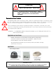
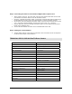
Pan Tilt Controller Interface Module ① ② ②DVR INPUT CONNECTOR ①CAMERA INPUT CONNECTOR ③ ③6PIN DIP SWITCH Port Description Connection Type To Camera RS-485 data input/ video input 6 Pin DIN jack To DVR Serial data output / video output 6 Pin DIN jack SW 1 -6 Camera ID selection 6 Pin DIP switch TO CAMERA - transmits the Pan/Tilt control signals from the VistaPro 4 to the DCP1000 Dome Camera - receives the video signal from the DCP1000 Camera to the VistaPro 4.
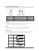
INSTALLATION Ensure electrical power is not connected to the dome camera and PC system during installation. DIAGRAM SHOWING TYPICAL SET-UP RS-232C to RS-485 CONVERTER RS-485(+) RS-485(-) 65ft 6Pin Din Cable Pan/Tilt Dome Camera RS-232C (to PC COM Port) 7ft RS485 Cable PT Interface DC12V VIDEO (VistaPro 4 Main Board) Important Note: For the P/T/Z Camera Model setting in the Camera menu of Setup in the VistaPro4, the DCP1000 is the “DYNACOLOR” camera in the drop down menu.
Step 2: Connecting the Camera to the VistaPro4 Digital Video Capture Card At the location of the PC, plug the other end of the 65’ Camera DIN cable into the DIN port labeled “To Camera” found on the PT interface module. Using the 7’ RS-485 Connection Cable, connect the end terminated with the DIN plug to the port labeled “To DVR” (next to the DIP switches) on the PT Interface module.