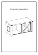
Assembly Instructions P.
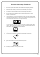
General Assembly Guidelines I. Ensure that all parts and hardware are available before beginning assembly. II. Follow each step carefully to ensure the proper assembly of this product. III. Two people are recommended for ease in the assembly of this product. IV. The three main types of hardware used to assemble this product are: wood dowels, screws and bolts. V. The provided glue is to secure wood dowels in place.
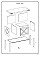
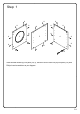
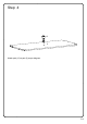
Parts List 1 7 7 6 4 5 8 3 12 2 10 11 9 13 P.
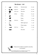
Hardware List A Ø8x30mm Wooden dowel 24 pcs B Ø6x35mm Cam bolt 20 pcs C Ø15x11mm Cam lock 20 pcs D Ø30mm Sticker 20 pcs E Pulley 2 pcs F Pulley 2 pcs Screw 16 pcs H Shelf support pin 4 pcs J Plastic wedge 8 pcs Screw 8 pcs Glue tube 1 pc G K L Ø3x12mm Ø3x17mm Philips head screwdriver required for assembly (not included) The hardware quantities listed above are required for proper assembly. Some extra hardware may also have been included. P.
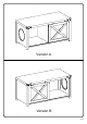
Version A Version B P.
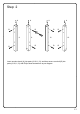
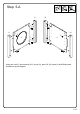
Step 1 A A A A A A B 4 5 B A A A 3 A A A A A A A B B Insert wooden dowel (A) into parts (3,4,5), and then secure cam bolt (B) into parts (3,4) with Philips head screwdriver as per diagram . P.
Step 2 A A A B B 11 B A 9 B B 12 B 10 B B Insert wooden dowel (A) into parts (9,10,11,12), and then secure cam bolt (B) into parts (9,10,11,12) with Philips head screwdriver as per diagram P.
Step 3 B B B B 1 B B A A B 2 B A A Insert wooden dowel (A) into part (2), and then secure cam bolt (B) into parts (1,2) with Philips head screwdriver as per diagram P.
Step 4 13 2 Attach part (13) to part (2) as per diagram. P.
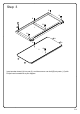
1 Step 5-A 11 C 2 3 12 C 9 10 C C 3 4 C C C C Using cam lock (C) secure parts (9,11) to part (3), parts (10,12) to part (4) with Philips head screwdriver as per diagram. P.
1 Step 6-A 2 3 3 C 2 C Using cam lock (C) secure part (2) to part (3) with Philips head screwdriver as per diagram. P.
1 Step 7-A 2 3 4 C C 2 Using cam lock (C) secure part (2) to part (4) with Philips head screwdriver as per diagram. P.
1 Step 8-A 2 3 5 C C 2 Using cam lock (C) secure part (5) to part (2) with Philips head screwdriver as per diagram. P.
Step 9-A 11 7 12 7 5 2 Put part (7) as per diagram. P.
1 Step 10-A 2 3 1 C C C C C 3 C 5 4 Using cam lock (C) secure part (1) into parts(3,4,5) with Philips head screwdriver as per diagram. P.
Step 11-A J K J Using screw (K) secure plastic wedge (J) with Philips head screwdriver as per diagram. P.
Step 12-A D D D D D Place sticker (D) cover the holes as per diagram. P.
Step 13-A H 5 H 4 H 6 H H Insert shelf support pin (H) into parts(4,5) as per diagram. Make sure you place shelf support pins (H) in the same level. So the shelf is not titled. Put part (6) into unit as per diagram. Tilt and rest the adjustable shelf (6) onto the shelf support pins. P.
Step 14-A G E G G F E 8 G F Using screw (G) attach pulleys (E,F) into part (8) with Philips head screwdriver as per diagram. P.
Step 15-A 1 E E 1 2 8 F 2 Pick up the door (8), and fit the pulley (F) over the slider rails on the bottom panel (2) ,then place the pulley (E) into top panel (1) , till it click into pulley (F) as per diagram. P.
Step 16-A Position the assembled unit at the desired location, if necessary adjust the floor leveler at the bottom of the support leg to level the unit. P.
Step 17 Version A Final Assembly P.
1 Step 18-B 11 C 2 3 12 C 9 10 C C 4 3 C C C C Using cam lock (C) secure parts (9,11) to part (4) , parts (10,12) to part (3) with Philips head screwdriver as per diagram. P.
1 Step 19-B 2 3 4 C 2 C Using cam lock (C) secure part (2) to part (4) with Philips head screwdriver as per diagram. P.
1 Step 20-B 2 3 3 C C 2 Using cam lock (C) secure part (2) to part (3) with Philips head screwdriver as per diagram. P.
1 Step 21-B 2 3 5 C C 2 Using cam lock (C) secure part (5) to part (2) with Philips head screwdriver as per diagram. P.
Step 22-B 12 7 11 7 5 2 Put part (7) as per diagram. P.
1 Step 23-B 2 3 1 C C C C C 3 C 4 5 Using cam lock (C) secure part (1) into parts(3,4,5) with Philips head screwdriver as per diagram. P.
Step 24-B J K J Using screw (K) secure plastic wedge (J) with Philips head screwdriver as per diagram. P.
Step 25-B D D D D D Place sticker (D) cover the holes as per diagram. P.
Step 26-B 5 H H 4 H 6 H H Insert shelf support pin (H) into parts(4,5) as per diagram. Make sure you place shelf support pins (H) in the same level. So the shelf is not titled. Put part (6) into unit as per diagram. Tilt and rest the adjustable shelf (6) onto the shelf support pins. P.
Step 27-B G E G G F E 8 G F Using screw (G) attach pulleys (E,F) into part (8) with Philips head screwdriver as per diagram. P.
Step 28-B 1 E E 1 8 2 F 2 Pick up the door (8), and fit the pulley (F) over the slider rails on the bottom panel (2) ,then place the pulley (E) into top panel (1) , till it click into pulley (F) as per diagram. P.
Step 29-B Position the assembled unit at the desired location, if necessary adjust the floor leveler at the bottom of the support leg to level the unit. P.
Step 30 Version B Final Assembly P.