
Owners manual


Building American Quality… With A Lifetime Warranty!
General Installation Notes:
Please read these instructions completely before beginning the
installation. If you have any questions please call.
Before beginning the installation, disconnect the negative battery
cable and use wheel chocks to block the vehicle's wheels. Do not
attempt to install or adjust this product while the engine is running.
Make sure the engine, transmission, body and frame are properly
grounded. We recommend applying anti-seize lubricant to all
aluminum threads before final assembly. Do not over tighten.
NOTE: Lokar’s Throttle Cable Kits are designed to work with Lokar
Throttle Pedals and Throttle Cable Brackets. This Throttle Cable is
designed to be Cut-To-Fit for your particular application.
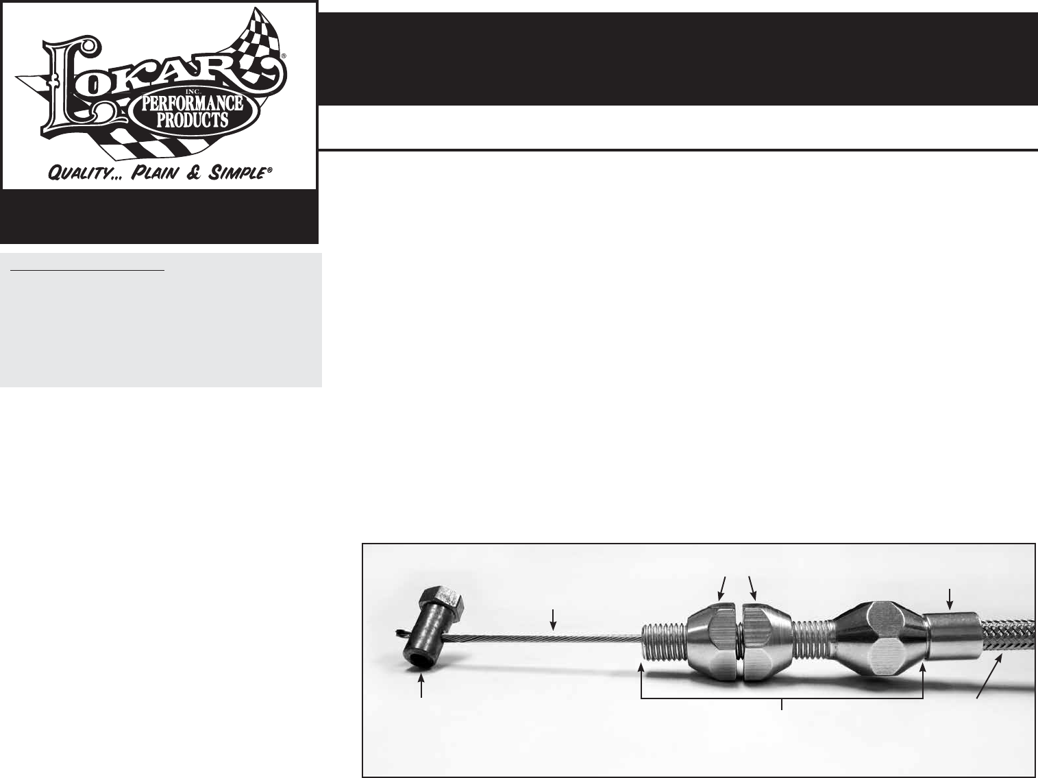
Refer to Figs. 1, 2 and 3 for the component names.
The GM Tuned-Port Injection (TPI) kit includes two throttle body fittings.
The aluminum throttle body fitting with two set screws fits early TPI
systems up through 1988 (Fig. 2). The brass throttle body fitting with
one set screw is used on 1989 and later TPI, LT1, and LT4 systems.
Step 1: If the Lokar Throttle Pedal and Throttle Cable Bracket have not
already been installed, do so now, following the instructions
provided with those parts.
Step 2: The throttle cable hole in the firewall must line up with the hole
in the throttle pedal. Determine exactly where the Throttle Cable
needs to pass through the firewall and drill a 5/16" hole.
Step 3: Remove the throttle body fitting and throttle cable adjuster from
the engine end of the new Lokar Throttle Cable. If you have
the braided stainless steel housing, make sure you DO NOT
remove the ferrule from the cable housing. Pull the inner wire
out of the cable housing.
Step 4: On the pedal end of the cable housing, remove the adjuster nut
from the firewall fitting. Insert the firewall fitting through the firewall
from the engine side, and reinstall the adjuster nut. Fig. 3
Step 5: Remove the front adjuster nut from the throttle cable adjuster
and insert the throttle cable adjuster into the throttle cable
bracket (bracket sold separately). Position the rear adjuster nut
so that the throttle cable bracket is approximately centered on
the threaded part of the throttle cable adjuster. Reinstall the
front adjuster nut. Fig. 4
TOLL FREE 1-877-469-7440 • tech@lokar.com • www.lokar.com
®
EFI Throttle Cable Installation Instructions
EFI Throttle Cable Installation Instructions
For GM TPI, LT1, LT4, Vortec, LS1, and Ram Jet 350
Ford EFI 1994-95, and Modular Engines
INS0068 Rev. 04/17/2017
Page 1
© 2005 Lokar, Inc.
Fig. 1
For GM TPI, LT1, LT4, Vortec, LS1, and Ram Jet 350
Ford EFI 1994-95, and Modular Engines
Step 6: Make sure that the inner wire is removed from the cable housing!
If the cable housing is braided stainless steel, slide the ferrule up the
housing towards the firewall, away from the end that is being cut.
DO NOT remove the ferrule from the braided stainless steel housing!
Fig. 5
If the cable housing is black universal, remove the ferrule.
Measure the distance between the throttle cable adjuster and the
firewall fitting. Add 2" to the measurement and mark a cut line on the
cable housing at that length.
NOTE: The cable housing must not be straight between the throttle
cable adjuster and the firewall. There must be some slack to allow for
engine movement.
If the Throttle Cable has the braided stainless steel housing, wrap tape
around the area to be cut and use a cutoff wheel or fine-toothed hacksaw
to cut the cable housing. If it has a black universal housing, cut the cable
housing with heavy duty 8" diagonal cutting pliers or a hacksaw. Lokar
recommends Klein brand Diagonal Cutting Pliers, # D2000-28 available
at The Home Depot or through W. W. Graingers, Part # 4A838.
After cutting the cable housing, put the ferrule back in place at the
end of the cable housing. Insert the cable housing and ferrule into the
throttle cable adjuster. The ferrule does NOT need to be crimped or
otherwise attached in place.
Step 7: Reinstall the inner wire into the cable housing from inside the
passenger compartment. Connect the clevis on the new Lokar
Throttle Cable to the throttle pedal.
NOTE: If you are using a factory style pedal with a ball type
connection, the clevis can be removed by simply sliding it off of the
inner wire before you install the inner wire into the cable housing.
Step 8: Depress the throttle pedal to the floor and hold the throttle
body at the wide open throttle position. Pull all the slack out
of the inner wire. Mark the inner wire at the spot that the
throttle body fitting attaches to the throttle lever or fits into the
hole on the pulley.
Step 9: On 1988 and earlier TPI with a throttle lever, cut the inner
wire 1/4" shorter than the mark. On all others with a throttle
pulley, cut the inner wire 1/4" longer than the mark. MAKE
SURE you are not cutting the inner wire too short! Install the
throttle body fitting onto the end of the inner wire and tighten
the set screw(s).
Step 10: Still holding the throttle wide open, release the throttle pedal
so that it creates slack in the inner wire. Attach the throttle
body fitting to the throttle lever or insert it into the slot or
groove in the pulley.
Step 11: Release the throttle. Take any slack out of the inner wire
with the adjuster nuts. The throttle should be able to close
fully, and the pedal should touch the floor at the same time
the throttle reaches wide open. NOTE: Check to make sure
there is no binding of the Throttle Cable at both the throttle
pedal and at the throttle linkage before starting the engine
or driving the vehicle.
See Fig. 6 for an example of the Throttle Cable installed on
a GM LS1 engine, Fig. 7 for an early TPI installation, and
Fig. 8 for an LT1/LT4 installation.
Inner Wire
Throttle Body Fitting
(Varies per Application)
Ferrule (DO NOT REMOVE
if the Cable Housing is
braided stainless steel)
Cable
Housing
Throttle Cable
Adjuster
All Except 1988 and Earlier GM TPI
Adjuster Nuts