K8SLI Copyright All rights are reserved. No part of this publication may be reproduced, transmitted, transcribed, stored in a retrieval system or translated into any language or computer language, in any form or by any means, electronic, mechanical, magnetic, optical, chemical, manual or otherwise, without the prior written permission of the company. Brands and product names are trademarks or registered trademarks of their respective companies.
You have to know !!! 0 The images and pictures in this manual are for reference only and may vary slightly from actual product installation depending on specific hardware models, third party components and software versions. 0 Unplug your computer when installing components and configuring switches and pins. 0 This mainboard contains very delicate IC chips. Use a grounded wrist strap when working with the system. 0 Do not touch the IC chips, leads, connectors or other components.
K8SLI nVIDIA® nForce4 SLI Supports Socket 939 AMD® AthlonTM 64 Processor AMD® AthlonTM 64 FX Processor USER Manual Dimensions (ATX form-factor): z 194mm x 295mm (WxL) Operating System: z Supports most popular operating systems: Windows® 2000/XP etc.
Contents CHAPTER 1. GETTING STARTED ............................................................1 INTRODUCTION.......................................................................................................... 1 SPECIFICATION .......................................................................................................... 2 CONFIGURATION ....................................................................................................... 5 Layout of K8SLI...................................
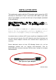
INSTALLATION NOTE This mainboard complies with the ATX standard, which means the ACPI connector on this board is 2-pin. If the Power LED cable of your case uses a 3-pin adapter, you must use the 2-pin to 3-pin adapter (contained in the packaging).
Locate the Power LED cable attached to the case. If the Power LED cable has a 3-pin adapter, you must use the 2-pin to 3-pin adapter which comes with the packaging. The heads of the power cables usually have a triangular mark which indicates the positive electrode(+). Connect the 3-pin end of the adapter to the Power LED cable, matching up the positive electrodes(+).
K8SLI Chapter 1. Getting Started Introduction Congratulations on choosing the K8SLI mainboard! It based on nVIDIA® nForce4 SLI chipset. It also supports AMD® AthlonTM 64 / AMD® AthlonTM 64 FX Processor. The K8SLI mainboard provides 4 sockets using 184 pin DDR SDRAM (Dual channel). You can install DDR400/ 333/ 266 (PC3200/ 2700/ 2100) SDRAM. It supports install up to 4GB memory size.
K8SLI Specification CPU: z Supports Socket 939 z Supports AMD® AthlonTM 64 / AMD® AthlonTM 64 FX Processor z HyperTransportTM Link z - supports 16-bit to be capable of operating up to 1GHz (2000 MT/s) with a bandwidth of up to 2 Gbytes/s in each direction Chipset: z Single Chip – nVIDIA® nForce4 SLI z I/O Controller – Winbond Super I/O W83627HF-AW z AC’97 Codec – Realtek ALC655 z GB LAN PHY – Vitesse CIS8201 DRAM Memory: z Supports DDR400 ( DDR333 (PC2700)/ DDR266 (PC2100) SDRAM z Suppor
K8SLI LAN PHY Chip (Vitesse CIS8201): z 10/ 100/ 1000 Mbps Ethernet support Universal Serial Bus: z Supports up to eight USB ports for USB interface devices z Supports USB 2.0 Enhanced Host Controller Interface (EHCI) and dual USB 1.
K8SLI ABS (Albatron BIOS Security): z Supports ABS (Albatron BIOS Security) card (optional) z Provides BIOS backup function Green Functionality: z Supports Phoenix-Award BIOS ™ power management functionality z Contains an inactivity power down timer that can be set from 1 to 15 minutes z Wakes from power saving sleep mode with any keyboard or mouse activity Shadow RAM: z This mainboard is equipped with a memory controller providing shadow RAM and support for ROM BIOS Flash Memory: z Supports f
K8SLI Configuration Layout of K8SLI 5
K8SLI Hardware Installation This section will assist you in quickly installing your system hardware. Wear a wrist ground strap before handling components. Electrostatic discharge may damage your system components. CPU Processor Installation This mainboard supports AMD® AthlonTM 64/ 64FX processor using a Socket 939. Before building your system, we suggest you visit the AMD website and review the processor installation procedures. http://www.amd.com CPU Socket 939 Configuration Steps: 1. 2.
K8SLI FAN Headers Three power headers are available for cooling fans, which play an important role in maintaining the ambient temperature in your system. Attention We strongly recommend that you use a CPU fan sink with your CPU. You can attach the CPU fan to the CPUFAN header. Memory Installation The K8SLI mainboard contain 4 sockets, which use 184- pin DDR SDRAM with a total memory capacity of up to 4 GB. You can install unbuffered DDR400/ 333/ 266(PC3200/ 2700/ 2100) SDRAM.
K8SLI To Enable Dual-Channel DDR, the following conditions must be met: 1.You must use either DIMM1 & DIMM2 together or DIMM3 & DIMM4 together or all four DIMM slots together. If you want to use only one DIMM, you must use DIMM1 or DIMM3. 2.You must use matching DIMM configurations between DIMM1 & DIMM2. You must use matching DIMM configurations between DIMM3 & DIMM4. z Same Density (128MB, 256MB, 512MB, etc.
K8SLI RAM Module Installation: The following instructions explains memory module installation for these mainboards: 1. Before install your RAM module, please make sure that the power supply is UNPLUGGED. Pull the white plastic tabs at both ends of the slot away from the slot. 2. Match the notch on the RAM module with the corresponding pattern in the DIMM slot. This will ensure that the module will be inserted with the proper orientation. Attention: There’s a little red led beside the DIMM slots.
K8SLI Back Panel Configuration PS/2 Mouse & PS/2 Keyboard Connectors: KB/MS This mainboard provides a standard PS/2 mouse connector and PS/2 Keyboard connector. The pin assignments are described below: PS/2 Mouse PS/2 Keyboard Pin Assignment Pin Assignment 1 Data 4 +5 V (fused) 2 No connect 5 Clock 3 Ground 6 No connect Serial and Parallel Interface Ports This mainboard comes equipped with one serial port, one parallel port and one SPDIF out RCA port.
K8SLI SPDIF out connectors S/PDIF (Sony/Philips Digital Interface) is an audio transfer file format which provides high quality audio using optical fiber and digital signals. This mainboard is capable of a delivering audio output through this SPDIF connector. USB & GBLAN Connectors: USB/ GBLAN There are four USB connectors on the back panel. These USB connectors are used to attach to USB devices such as: keyboards, mice and other USB devices. You can plug the USB devices directly into this connector.
K8SLI Audio Port Connectors: Sound The K8SLI comes equipped with three Audio Ports. The three ports, Mic-in, Line-in and Front Speaker-out are standard audio ports that provide basic audio functionality. After you install the 5.1 Channel drivers for K8SLI and setup 5.1 channel Audio effect, the three audio ports are enabled for 5.1 channel and supporting two speakers each. Line In Connects to an external audio device such as a CD player, tape player or other audio devices that provide audio out.
K8SLI Front Panel Indicator: SW/LED、SPEAKER HD LED (Hard Drive LED Connector) This connector can be attached to an LED on the front panel of a computer case. The LED will flicker during disk activity. This disk activity only applies to those IDE drives directly attached to the system board. RST SW (Reset Switch Connector) This connector can be attached to a momentary SPST switch. This switch is normally left open. When closed it will cause the mainboard to reset and run the POST (Power On Self Test).
K8SLI Connectors Floppy Disk Connector: FDC The mainboard provides a standard floppy disk connector (FDC) that supports 360K, 720K, 1.2M, 1.44M and 2.88M floppy diskettes. This connector supports the floppy drive ribbon cables provided in the packaging. Hard Disk Connectors: IDE1/ IDE2、SATA1/ 2/ 3/ 4 The mainboard has a 32-bit Enhanced PCI IDE Controller that supports Ultra ATA 66, Ultra ATA 100 and Ultra ATA 133. It has two HDD connectors, IDE1 and IDE2.
K8SLI Headers & Jumpers Front USB Headers (Yellow): USB1/ USB2 This mainboard provides 2 USB headers on the board allowing for 4 additional USB ports. To make use of these headers, you must attach a USB bracket/cable with USB ports (some models will come packaged with a USB 4-port bracket-cable). The optionally packaged bracket will have two connectors that you can connect to the headers (USB1, USB2). The other end (bracket containing the USB ports) is attached to the computer casing.
K8SLI Infrared Header: IrDA (Optional) This IrDA connector can be configured to support wireless infrared and is used to attach to an infrared sensing device. After the IrDA interface is configured, you can use this connector for connectionless data transfer to and from portable devices such as laptops and PDAs. Game Port Header: GAME PORT(Optional) There is a game port header on these mainboards.
K8SLI ABS (Albatron BIOS security) Header: BIOSCN1 This mainboard includes one ABS header (BIOSCN1) for the ABS card which can provide a second BIOS for the mainboard in case the original BIOS is damaged. To set up the jumper on the ABS card, please refer to figure1. (Attention: Whether you want to use this function or not, removing this jumper cap from the ABS card is interdictory.) Attention: There are two jumper caps on the ABS header (BIOSCN1). One is in pin1 -2, and the other is in pin3 -4.
K8SLI Clear CMOS Jumper: JP1 The “Clear CMOS” jumper is used when you cannot boot your system due to some CMOS configuration such as a password that is forgotten. This jumper allows you to reset the CMOS configurations, and then reconfigure. The following steps explain how to reset your CMOS configurations when you have forgotten your system password. 1. Turn off your system and disconnect the AC power cable. 2. Set JP1 to OFF (2-3 Closed). 3. Wait several seconds. 4. Set JP1 to ON (1-2 closed). 5.
K8SLI Audio Connectors CD-ROM Audio-In Header: CD-IN This header is used to connect to a CD-ROM / DVD audio cable. Front Panel Audio Header: FRONT AUDIO You can use the Front Panel Audio header (FRONT AUDIO) to connect to a separate audio bracket or to connect to case embedded audio equipment. The Front AUDIO header provides MIC-in and Line–out functionality and cannot be used simultaneously with the back panel mic and speakers. An SPDIF/Audio bracket is optionally packaged with some models.
K8SLI SPDIF & FRONT AUDIO bracket (optional) You can connect the bracket to the SPDIF and FRONT AUDIO Headers (This photo can be varied with different models). Slots The slots in this mainboard are designed for expansion cards used to complement and enhance the functionality of the mainboard. PCI-Express slots: PCIE1/ PCIE2/ PCIE3/ PCIE4 PCI-E x 8 slots are for installing PCI-Express graphics cards. PCI-E x 1 slot is for expansion cards which fit the PCI-E x 1 slot. The K8SLI supports SLI technology.
K8SLI Power Supply Attachments ATX Power Connector: ATX_PWR、ATX_12V This mainboard requires two ATX power connections. The first is a 24-pin connector and the second is a 4-pin connector. Attach the 4-pin connector first and then attach the 24-pin connector. Make sure the connectors are secure before applying power.
K8SLI Chapter 2. BIOS Setup Introduction This section describes PHOENIX-AWARD™ BIOS Setup program which resides in the ROM BIOS firmware. The Setup program allows users to modify the basic system configuration. The configuration information is then saved to CMOS RAM where the data is sustained by Li-battery after power-down. The BIOS provides critical low-level support for standard devices such as disk drives, serial ports and parallel ports.
K8SLI Supported CPUs This PHOENIX-AWARD™ BIOS supports the AMD® AthlonTM 64 / 64 FX CPU. Key Function In general, you can use the arrow keys to highlight items, press to select, use the and keys to change entries, press for help and press to quit. The following table provides more detail about how to navigate within the BIOS Setup program.
K8SLI Main Menu When you enter the PHOENIX-AWARD™ BIOS Utility, the Main Menu will appear on the screen. The Main menu allows you to select from several configuration options. Use the left/right arrow keys to select a particular configuration screen from the top menu bar or use the down arrow key to access and configure the information below.
K8SLI Main Menu Setup Configuration Options Item Options Description Date mm dd yyyy Set the system date. Note that the ‘Day’ automatically changes when you set the date. Time Hh: mm: ss Set the current time of the system. IDE Primary Master Options contained in sub menu. Press to enter the sub menu. IDE Primary Slave Options contained in sub menu. Press to enter the sub menu. IDE Secondary Options contained in Master sub menu. Press to enter the sub menu.
K8SLI Advanced BIOS Features Removable Device Priority Select removable device priority. Just like floppy, LS120, ZIP-100, USB-FDD and USB-ZIP. Hard Disk Boot Priority Select hard disk boot priority. CD-ROM Boot Priority Select CD-ROM boot priority. First /Second/Third Boot Device Select the order in which devices will be searched in order to find a boot device.
K8SLI Boot Up Floppy Seek When Enabled, the BIOS tests (seeks) floppy drives to determine whether they have 40 or 80 tracks. Only 360-KB floppy drives have 40 tracks. Drives with 720KB, 1.2MB, and 1.44MB capacity all have 80 tracks. Because very few modern PCs have 40-track floppy drives, we recommend that you set this field to “Disabled”. Options: Enabled、Disabled (default) Advanced BIOS Features Virus Warning Set the virus warning feature for IDE hard disk boot sector protection.
K8SLI Typematic Delay (Msec) The delay before keystrokes begin to repeat. Options: 250 (default)、500、750、1000 APIC Mode By enabling this option, “MPS version control for OS” can be configured. Options: Disabled、Enabled (default) MPS Version Control For OS The 1.1 version is the older version that supports 8 more IRQs in the Windows NT environment. Choose the new 1.4 version for Windows 2000 and Windows XP. Options: 1.4 (default)、1.
K8SLI RAS# to CAS# delay (Trcd) Select the DRAM delay time when being read. Options: Auto、2T、3T、4T、5T、6T、7T Row precharge Time (Trp) You can set the time to precharge. Options: Auto、2T、3T、4T、5T、6T、7T 1T/2T Memory Timing Use this item to select the memory timing that you installed. Options: 1T、2T(default) System BIOS Cacheable When enabled, accesses to system BIOS ROM addressed at F0000H-FFFFFH are cached, provided that the cache controller is enabled.
K8SLI PCI / VGA Palette Snoop Some graphic controllers that are not VGA compatible take the output from a VGA controller and map it to their display as a way to provide boot information and VGA compatibility. Options: Disabled (default)、Enabled PCI Latency Timer (CLK) This item allows you to set up the PCI Latency Time (0-255). If you select the “32” it will optimize PCI speeds.
K8SLI HT Ratio This item allows you to set Hyper Transport Frequency. Options: Auto(default)、1x、2x、3x、4x、5x HT Frequency This item displays the result of your HT Ratio setting PCIE Clock This item allows you to select PCIE clock form 100 Mhz(default) to 145Mhz. PCIE Spread Spectrum The Spread Spectrum function can reduce the EMI (Electromagnetic Interference) generated. Options: Enabled (default)、Disabled CPU Voltage (Volt) This item allows you to adjust your CPU core voltage.
K8SLI Integrated Peripherals Init Display First With systems that have multiple video cards, this option determines whether the primary display uses a PCI slot or an PCIEx slot. Options: PCIEx、PCI Slot (default) IDE Function Setup If you highlight the “IDE Function Setup” label and then press the enter key, it will take you to a submenu with the following options: OnChip IDE Channel 0/1 The mainboard chipset contains a PCI IDE interface with support for two IDE channels.
K8SLI Primary / Secondary /Master / Slave UDMA Ultra DMA 100 functionality can be implemented if it is supported by the IDE hard drives in your system. As well, your operating environment requires a DMA driver (Windows 95 OSR2 or a third party IDE bus master driver). If your hard drive and your system software both support Ultra DMA 100, select “Auto” to enable BIOS support.
K8SLI Onboard Device If you highlight the “Onboard Device” label and then press the enter key, it will take you to a submenu with the following options: OnChip USB This option should be enabled if your system has a USB port installed on the system board. You will need to disable this feature if you add a higher performance controller. Options: V1.1+V2.0 (default)、Disabled、V1.
K8SLI Onboard FDC Controller Select “Enabled” if your system has a floppy disk controller (FDC) installed on the system board and you wish to use it. If you install an add-in FDC or the system has no floppy drive, select “Disabled”. Options: Enabled (default)、Disabled Onboard Serial Port Select an address and corresponding interrupt for the first/ second serial port.
K8SLI Power Management The Power Management Setup Menu allows you to configure your system to utilize energy conservation features as well as power-up/ power-down options. ACPI Suspend Type The item allows you to select the suspend type using the ACPI operating system. Options: S1 (POS) (default) Power on Suspend S3 (STR) Suspend to RAM S1 & S3 POS and STR Power Management There are three options of Power Management: 1. Min. Power Saving Minimum power management HDD Power Down = 15 minutes 2. Max.
K8SLI Note: If you select Min. or Max. Power Saving modes, the “HDD Power Down” value will fixed. User Define、Min Saving、Max Saving Video Off Method This option determines the manner in which the monitor goes blank. Options: V/H SYNC+Blank This selection will cause the system to turn off the vertical and horizontal synchronization ports and write blanks to the video buffer. Blank Screen This option only writes blanks to the video buffer. DPMS Support (default) Initial display power management signaling.
K8SLI RTC Wake Up When “Enabled”, you can set the date and time at which the RTC (real-time clock) alarm awakens the system from Suspend mode. Options: Enabled、Disabled (default). Day of Month Alarm You can choose which date of the month the system will boot up. This field is only configurable when “RTC Wake Up” is set to “Enabled”. Min=0 Max=31 Time (hh: mm: ss) Alarm You can choose the hour, minute and second the system will boot up.
K8SLI Load Defaults Load System Default Settings Load System Default Settings. Load System Turbo Settings Load System Turbo Settings. Load CMOS From BIOS Load defaults from flash ROM for systems without batteries. Save CMOS To BIOS Save defaults to flash ROM for systems without batteries.
K8SLI Exit Menu Save & Exit Setup Save all configuration changes to CMOS (memory) and exit setup. A confirmation message will be displayed before proceeding. Exit Without Saving Abandon all changes made during the current session and exit setup. A confirmation message will be displayed before proceeding.
K8SLI Chapter 3: Software Setup Software List Category Microsoft DirectX 9.0c nForce Chipset Driver Trend PC-Cillin 2004 Acrobat Reader 5 Platform Windows 98 /ME /2000 /XP Windows 2000 /XP Windows 98 /ME /2000 /XP Windows 98 /ME /2000 /XP Software Installation Place the Driver CD into the CD-ROM drive and the Installation Utility will auto-run. You can also launch the Driver CD Installation Utility manually by executing the nVIDIA.exe program located on the Driver CD.
K8SLI ¾ ¾ 2. Microsoft DirectX – provides software of Microsoft DirectX nForce Chipset Driver – Provides all the drivers needed for the chipset. It also includes the audio driver. Note: We recommend that you install the “nVIDIA IDE SW” during Windows® XP installation. Click the “Tool Menu” button and the screen will display as below. This screen displays all of the software that you can install from the Driver CD.
K8SLI Chapter 4: Troubleshooting Problem 1: No power to the system. Power light does not illuminate. Fan inside power supply does not turn on. Indicator lights on keyboard are not lit. Causes: 1. Power cable is unplugged. 2. Defective power cable. 3. Power supply failure. 4. Faulty wall outlet; circuit breaker or fuse blown. Solutions: 1. Make sure power cable is securely plugged in. 2. Replace cable. 3.Contact technical support. 4.Use different socket, repair outlet, reset circuit breaker or replace fuse.
K8SLI Problem 4: System only boots from the CD-ROM. The hard disk can be read and applications can be used but booting from the hard disk is impossible. Causes: Hard Disk boot sector has been corrupted. Solutions: Back up data and applications files. Reformat the hard drive. Re-install applications and data using backup disks. Problem 5: Error message reading “SECTOR NOT FOUND” displays and the system does not allow certain data to be accessed.
K8SLI Problem 10: Keyboard failure. Causes: Keyboard is disconnected. Solutions: Reconnect keyboard. Replace keyboard if you continue to experience problems. Problem 11: No color on screen. Causes: 1. Faulty Monitor. 2. CMOS incorrectly set up. Solutions: 1. If possible, connect monitor to another system. If no color appears, replace monitor. 2. Call technical support. Problem 12: The screen displays “C: drive failure.” Causes: Hard drive cable not connected properly. Solutions: Check hard drive cable.
K8SLI Appendix I: 5.1 Channel Setup 1. After get into the system, click the audio icon from the Windows screen. 2. Click Speaker Configuration button, you can see the screen like the picture below. 3. You can choose 2, 4 or 6 channels by your speakers. 2 Channels 4 Channels 6 Channels Super 5.1 Channel Audio Effect This mainboard comes with an ALC655 Codec which supports high quality 5.1 Channel audio effects.
K8SLI Appendix II: RAID Setup Introduction to RAID RAID (Redundant Array of Independent Disks) technology is a sophisticated disk management system that manages multiple disk drives. It enhances I/O performance and provides redundancy in order to prevent the loss of data in case of individual disk failure. The RAID facility on this board provides RAID 0, RAID 1, RAID 0+1 and RAID SPAN. The total number of drives you can apply depends on the number of connectors on your board.
K8SLI NVIDIA RAID Utility Configuration The NVIDIA RAID Utility is used to configure RAID disk management into your hard disks. This section will explain how to setup and maintain your RAID disk drives.
K8SLI 0.0.M = PATA1 (master drive) 0.0.S = PATA1 (slave drive) 0.1.M = PATA2 (master drive) 0.1.S = PATA2 (slave drive) 1.0.M = SATA1 1.1.M = SATA2 Creating New RAID Array 1. The first screen you will see upon initial configuration is the “Define New Array” screen. First, tab over to the “RAIDMode” text box and press . The pop up menu will display as shown below.
K8SLI 3. Next, in the “Free Disks” section, you can use the up/down arrow keys to select disks to be used in your RAID array. After highlighting a disk, use the right-arrow key to activate the disk as part of the RAID Array. The selected disk will move over to the “Array Disks” section. You can use the left-arrow key to reverse your selection. After you finish selecting all your disks, Press . A confirmation message will display as shown below. Then press to complete the RAID array creation. 4.
K8SLI Deleting an Array 1. You can delete an existing array on the “Array Detail” screen. Press the key. A warning/confirmation message will display (as shown below). Press to confirm. 2. After the array is successfully deleted, the screen will display as shown below.
K8SLI Rebuilding a RAID Mirrored Array This section applies to Mirrored or Striped/Mirrored RAID configurations and describes how to reestablish the integrity of a mirrored environment after replacing one of the drives (typically because of a single disk failure). After replacing the errant drive, the rebuild process will move data from its mirrored sibling drive (the drive with information still intact) to the newly installed drive. This only applies to mirrored configurations (RAID 1 and RAID 0+1).
K8SLI Installing RAID Drivers during Windows Installation Installation of RAID drivers is done during the Windows installation. These steps assume that the hard disks have already been connected to either the PATA or SATA connectors. It is also assumed that the BIOS RAID Utility has already been configured (see NVIDIA BIOS RAID Utility Configuration section) and you have begun the Windows operating system installation.
K8SLI Appendix Ⅲ: SLI (Scalable Link Interface) Introduction: nVIDIA® SLI (Scalable Link Interface) technology allows your computer to use two identical nVIDIA® SLI-ready PCI Express™ graphics cards at once. Combining two nVIDIA® SLI-certified graphics cards in a single system could essentially double your graphics performance (up to 2x). Requirements: 1. Two identical SLI-ready graphic cards. 2. The driver of the graphic card must supports the SLI technology.
K8SLI Installation When installing two identical SLI-ready graphic cards, remember to connect the golden fingers of two graphic cards with the bridge PCB. You can only connect the monitor with the graphic card which is in the PCIE2 slot. Make sure that you have already installed your chipset driver and your SLI-ready graphic card driver. Then just follow the instructions below to set up your SLI function. 1.
K8SLI 2. On the next screen (below), select the “SLI multi-GPU” item which is on the left of the sub window. And select the checkbox of “Enable SLI multi-GPU” in the main screen. Click on the “Apply” button to complete the configuration.