Revision C: • SPECIFICATION has been corrected. Please void OB450 REVISED EDITION-B. INDOOR UNIT No.
Revision A : • PARTS LIST has been revised. (10-1.8, 10-2.8) Revision B : • MSZ-A•NA- 1 and MSY-A•NA- 1 Remote controller has been changed. Revision C : • SPECIFICATION has been corrected. Powerful has been added. (Airflow , Sound level) 1 TECHNICAL CHANGES MSZ09UN MSZ12UN MSH15TN MSH17TN MSZ-A09NA MSZ-A12NA MSZ-A15NA MSZ-A17NA MSH24WN MS15TN MS17TN MS24WN MSZ-A24NA MSY-A15NA MSY-A17NA MSY-A24NA 1. Control method between indoor and outdoor has been changed. 2. Indoor fan motor has been changed. 3.
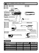
2 PART NAMES AND FUNCTIONS MSZ-A09NA MSZ-A12NA MSZ-A15NA MSZ-A17NA MSY-A15NA MSY-A17NA MSZ-A24NA MSY-A24NA Front panel Air inlet Heat exchanger Panel Air cleaning filter (Anti-Allergy Enzyme Filter, Blue bellows type) Catechin air filter Air outlet Vertical vane Remote controller Horizontal vane Line flow fan MSZ-A09NA MSZ-A12NA MSZ-A15NA MSZ-A17NA MSY-A15NA MSY-A17NA Display section Operation section (When the front panel is opened) Operation Indicator lamp Emergency operation switch MSZ-A24NA
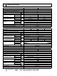
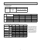
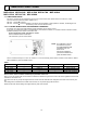
3 SPECIFICATION Indoor unit model MSZ-A09NA MSZ-A12NA External finish White Power supply V, phase, Hz 208/230, 1, 60 Max.-fuse size (time delay) / Disconnect switch A 15 Min. circuit ampacity A 1.0 Fan motor Airflow Low–Med.–High–Powerful F.L.A COOL Dry (Wet) HEAT Moisture removal Sound level Low–Med.–High–Powerful CFM 0.76 152-229-307-338 (134-205-275-303) 159-222-307-321 pt./h COOL dB(A) HEAT Cond. drain connection O.D. 2.3 3.
3-1. OPERATING RANGE (1) POWER SUPPLY Rated voltage Guaranteed Voltage (V) 208/230 V 1 phase 60 Hz Indoor unit Min.187 208 230 Max.253 (2) OPERATION Intake air temperature (°F) Mode Condition Indoor Outdoor DB 80 90 67 Standard temperature Maximum temperature Cooling Minimum temperature Maximum humidity Standard temperature Heating Maximum temperature Minimum temperature WB 67 73 57 DB 95 115 14 60 67 60 47 75 14 78% WB — — — — 70 80 70 43 65 13 3-2.
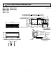
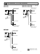
OUTLINES AND DIMENSIONS MSZ-A09NA MSY-A15NA MSZ-A12NA MSY-A17NA MSZ-A15NA MSZ-A17NA Indoor unit 8-7/8 2-3/16 7/8 hole 7/8 10-1/8 8-7/16 1-5/8 30-11/16 8-7/8 2-3/16 6-1/8 2-3/16 6-1/8 13-3/16 1-3/4 12-5/8 Air in 8-1/4 Wall hole 3/16 11-3/4 24-9/16 Liquid line Gas line Insulation 1/4 19-11/16 3/8 16-15/16 1-3/8 O.D 3/4 I.D Drain hose 5/8 (Connected part O.D) 4 Air out 3/4 6-1/4 2-5/16 2-9/16 Installation plate { 2-1/8 2-3/4 1/8 Installation plate and MSY-A•NA- are excluded.
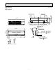
MSZ-A24NA MSY-A24NA Unit : inch Installation plate Indoor unit 5/16 6-13/16 16-5/16 16-5/16 6-13/16 1-7/8 3-7/8 1/8 1-7/8 10-1/16 42-1/16 12-3/8 3-7/8 Wall hole 3 10-1/4 43-5/16 Air in 3/16 Installation plate 12-13/16 { 2-3/16 31-1/8 9-15/16 Air out Wireless remote controller 7 1/4 19-11/16 5/8 16-15/16 1-15/16 O.D 1-1/4 I.D Drain hose 5/8 (Connected part O.
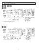
5 WIRING DIAGRAM MSZ-A09NA MSY-A15NA MSZ-A12NA MSY-A17NA MSZ-A15NA MSZ-A17NA MSZ-A24NA MSY-A24NA 8
6 REFRIGERANT SYSTEM DIAGRAM MSZ-A09NA MSZ-A12NA MSZ-A15NA MSY-A15NA MSZ-A17NA MSY-A17NA Refrigerant pipe ø1/2 (with heat insulator) Refrigerant pipe ø3/8 (with heat insulator) Indoor coil thermistor RT12(main) Indoor heat exchanger Indoor heat exchanger Flared connection Distributor Flared connection Room temperature thermistor RT11 Room temperature thermistor RT11 Flared connection Flared connection Refrigerant pipe ø1/4 (with heat insulator) Indoor heat exchanger Indoor coil thermistor RT
7 SERVICE FUNCTIONS MSZ-A09NA MSZ-A12NA MSZ-A15NA MSZ-A17NA MSZ-A24NA MSY-A15NA MSY-A17NA MSY-A24NA 7-1. TIMER SHORT MODE For service, set time can be shortened by short circuit of JPG and JPS the indoor electronic control P.C. board. The time will be shortened as follows. (Refer to 8-7.) Set time : 1-minute 1-second Set time : 3-minute 3-second (It takes 3 minutes for the compressor to start operation. However, the starting time is shortened by short circuit-of JPG and JPS.) 7-2. P.C.
7-3. AUTO RESTART FUNCTION When the indoor unit is controlled with the remote controller, the operation mode, the set temperature, and the fan speed are memorized by the indoor electronic control P.C. board. The “AUTO RESTART FUNCTION” sets to work the moment power has restored after power failure. Then, the unit will restart automatically. Operation If the main power has been cut, the operation settings remain. After the power is restored, the unit restarts automatically according to the memory.
3. Troubleshooting procedure 1) First, check if the OPERATION INDICATOR lamp on the indoor unit is flashing ON and OFF to indicate an abnormality. To make sure, check how many times the abnormality indication is flashing ON and OFF before starting service work. 2) Before servicing check that the connector and terminal are connected properly. 3) If the electronic control P.C. board is supposed to be defective, check the copper foil pattern for disconnection and the components for bursting and discoloration.
8-2. FAILURE MODE RECALL FUNCTION Outline of the function This air conditioner can memorize the abnormal condition which has occurred once. Even though LED indication listed on the troubleshooting check table (8-4.) disappears, the memorized failure details can be recalled. This mode is very useful when the unit needs to be repaired for the abnormality which doesn't recur. 1. Flow chart of failure mode recall function for the indoor/outdoor unit Those figures show about MSZ-A09/12/15/17.
2. Indoor unit failure mode table Left lamp of OPERATION INDICATOR lamp Not lighted Abnormal point (Failure mode) Normal Condition Correspondence — The room temperature thermistor short or 1-time flash every Room temperature open circuit is detected every 8 seconds dur0.5-second thermistor ing operation. Indoor coil 2-time flash The indoor coil thermistor short or open circuit 2.5-second OFF is detected every 8 seconds during operation.
8-3. INSTRUCTION OF TROUBLESHOOTING Start Indoor unit operates. Outdoor unit doesn't operate. Indoor unit operates. Outdoor unit doesn't operate normally. Indoor unit doesn't receive the signal from remote controller. OPERATION INDICATOR lamp on the indoor unit is flashing on and off. If blinking of OPERATION INDICATOR lamp cannot be checked, it can be checked with failure mode recall function. Outdoor unit operates only in Test Run operation. Outdoor unit doesn't operate even in Test Run operation.
8-4. TROUBLESHOOTING CHECK TABLE Before taking measures, make sure that the symptom reappears for accurate troubleshooting. When the indoor unit has started operation and detected an abnormality of the following condition (the first detection after the power ON), the indoor fan motor turns OFF and OPERATION INDICATOR lamp flashes. OPERATION INDICATOR No.
OPERATION INDICATOR No. 1 Abnormal point MXZ type Operation mode setting Operation indicator lamp Left lamp lights and lower lamp flashes. Lower lamp flashes. 2.5-second OFF Symptom Condition Correspondence The operation mode of the each indoor unit Outdoor unit is differently set to COOL (includes DRY) and • Unify the operation mode. operates but HEAT at the same time, the operation mode Refer to outdoor unit service indoor unit does of the indoor unit that has operated at first has manual.
8-6. TROUBLESHOOTING FLOW A Check of indoor fan motor The indoor fan motor error has occurred, and the indoor fan doesn't operate. Turn OFF the power supply. Pay careful attention to the high voltage on the fan motor connector CN211. Is there any foreign matter that interferes the rotation of the line flow fan? Turn ON the power supply, wait 5 seconds or more, and then press EMERGENCY OPERATION switch. Measure the supply voltage as follows within 12 seconds after EMERGENCY OPERATION switch is pressed.
B Check of remote controller and indoor electronic control P.C. board Check if the remote controller is exclusive for this air conditioner. Press OPERATE/STOP (ON/OFF) button on the remote controller. Is LCD display on the remote controller visible? Yes No (Not clear) Replace the batteries. (Refer to 8-1.4.) Remove the batteries, then set them back and press RESET button. (Refer to 8-1.4.) Check if the unit operates with the remote controller.
C Check of indoor electronic control P.C. board and indoor fan motor Turn OFF the power supply. Remove indoor fan motor connector CN211 and vane motor connector CN151 from the indoor electronic control P.C. board and turn ON the power supply. Does the unit operate with the remote controller? Does OPERATION INDICATOR lamp light up by pressing EMERGENCY OPERATION switch? No Measure the resistance between CN211 and of the indoor fan motor connector. Short/open circuit: Replace the indoor fan motor.
D How to check miswiring and serial signal error Turn OFF the power supply. Is there rated voltage in the power supply? Check the power supply. No Yes Turn ON the power supply. Is there rated voltage between outdoor terminal block S1 and S2? Yes Check the wiring. No Press EMERGENCY OPERATION switch once.
E Electromagnetic noise enters into TV sets or radios Is the unit grounded? No Ground the unit. Yes Is the distance between the antennas and the indoor unit within 9.91 ft., or is the distance between the antennas and the outdoor unit within 9.91 ft.? Yes Extend the distance between the antennas and the indoor unit, and/or the antennas and the outdoor unit. Yes Extend the distance between the TV sets and/or radios and the indoor unit, or the TV sets or radios and the outdoor unit.
8-7. Test point diagram and voltage MSZ-A09NA MSZ-A17NA MSZ-A12NA MSY-A15NA MSZ-A15NA MSY-A17NA Indoor electronic control P.C. board Power supply input 208/230 VAC } Varistor (NR11) Fuse (F11) 250 V 3.15 A Cement resistor (R111) Indoor fan motor (CN211) 294/325 VDC (-) Fiducial terminal of cathode side on measuring high-voltage DC 15 VDC (+)3-6 VDC (+)0 or 15 VDC Release of Auto restart function Solder the Jumper wire to JR07 (Refer to 7-3.
MSZ-A24NA MSY-24NA Indoor electronic control P.C. board Cement resistor (R111) Varistor (NR11) Power supply input 208/230 VAC } Release of Auto restart function Solder the Jumper wire to JR07 (Refer to 6-3.) Fuse (F11) 250 V 3.15 A Indoor fan motor (CN211) 294/325 VDC (-) Fiducial terminal of cathode side on measuring high-voltage DC Display P.C.
9 DISASSEMBLY INSTRUCTIONS <"Terminal with locking mechanism" Detaching points> The terminal which has the locking mechanism can be detached as shown below. There are two types ( Refer to (1) and (2)) of the terminal with locking mechanism. The terminal without locking mechanism can be detached by pulling it out. Check the shape of the terminal before detaching. (1) Slide the sleeve and check if there is a locking lever or not. (2) The terminal with this connector has the locking mechanism.
OPERATING PROCEDURE PHOTOS 2. Removing the electronic control P.C. board, the power monitor receiver P.C. board, SW P.C. board and the terminal block (1) Remove the horizontal vane, the panel (refer to 1.) and the corner box. (2) Remove the screw of the conduit cover, and conduit cover. (Photo 2 or Photo 3) (3) Remove the indoor/outdoor connecting wire. (4) Remove the switch holder from the electrical cover. (Photo 4) (5) Remove the screw of the electrical cover, and then the electrical cover.
OPERATING PROCEDURE PHOTOS 4. Removing the horizontal vane motor unit Photo 7 (1) Remove the horizontal vane, the panel (refer to 1.) and the corner box. (2) Remove the screws of the horizontal vane motor unit, and pull out the horizontal vane motor unit. (Photo 7) (3) Disconnect the connector from the horizontal vane motor unit. 5. Removing the indoor fan motor and the line flow fan (1) Remove the horizontal vane, the panel (refer to 1.) and the corner box.
9-2.MSZ-A24NA MSY-A24NA OPERATING PROCEDURE PHOTOS 1. Removing the front panel (1) Remove the screw caps of the front panel. Remove the screws. (2) Pull the panel down to your side slightly and unhook the catches at the top. Photo 1 Front panel Corner box Screws 2. Removing the electronic control P.C. board, the receiver P.C. board and the display P.C. board (1) Remove the front panel. (Refer to 1.) (2) Remove the corner box (3) Remove the screw of the electrical cover.
OPERATING PROCEDURE PHOTOS 4. Removing the vane motor Photo 4 (1) Remove the front panel. (Refer to 1.) (2) Remove the electrical cover. (Refer to 2.) Vane motors (3) Remove the lead wire of vane motor. (Refer to 3.) (4) Remove the R.L. holder. (5) Pull out the drain hose from the nozzle assembly and remove the nozzle assembly. (6) Remove the screws of the vane motor and disconnect the connector. (7) Remove the vane motor. Photo 5 Screws of the vane motor Vane motor 5.
10 PARTS LIST 10-1. PARTS LIST (non-RoHS compliant) MSZ-A09NA MSY-A15NA MSZ-A12NA MSY-A17NA MSZ-A15NA MSZ-A17NA 1. INDOOR UNIT STRUCTURAL PARTS 2. ACCESSORY AND REMOTE CONTROLLER 9 1 12 11 10 8 2 7 (See 10-1.5.) 3 4 5 6 1. INDOOR UNIT STRUCTURAL PARTS No. Part No.
MSZ-A09NA MSZ-A12NA MSZ-A15NA MSZ-A17NA MSY-A15NA MSY-A17NA 3. INDOOR UNIT ELECTRICAL PARTS AND FUNCTIONAL PARTS 1 18 17 14 15 16 2 3 4 5 6 11 10 9 12 No. Part No. Part name 1 E02 751 509 2 E02 001 504 3 E02 897 702 E02 A54 235 4 E02 A56 235 BEARING MOUNT SLEEVE BEARING DRAIN HOSE 5 E02 897 303 VANE MOTOR UNIT (HORIZONTAL) HORIZONTAL VANE POWER MONITOR RECEIVER P.C.
MSZ-A09NA MSZ-A12NA MSZ-A15NA MSZ-A17NA MSY-A15NA MSY-A17NA 4. INDOOR UNIT HEAT EXCHANGER 1 2 3 No. Part No. E02 A54 620 E02 A56 620 E02 815 666 2 E02 155 666 3 E02 151 667 1 Part name INDOOR HEAT EXCHANGER UNION (GAS) UNION (LIQUID) Q'ty/unit Symbol MSZMSYin Wiring Remarks Diagram A09NA A12NA A15NA A17NA A15NA A17NA 1 1 1 1 1 1 1 1 ø3/8 1 1 1 1 ø1/2 1 1 1 1 1 1 ø1/4 5. AIR CLEANING FILTER (ANTI-ALLERGY ENZYME FILTER) ● AIR CLEANING FILTER removes fine dust of 0.
MSZ-A24NA MSY-A24NA 6. INDOOR UNIT STRUCTURAL PARTS 7. INDOOR UNIT HEAT EXCHANGER 1 2 11 3 4 8 5 9 (See 10-1.10.) 12 13 6 7 6. INDOOR UNIT STRUCTURAL PARTS Part number that is circled is not shown in the illustration. Symbol No. Part No.
MSZ-A24NA MSY-A24NA 8. INDOOR UNIT FUNCTIONAL PARTS AND ELECTRICAL PARTS 1 9. ACCESSORY AND REMOTE CONTROLLER 17 18 21 22 2 3 4 9 16 10 5 6 12 11 15 8 7 13 15 14 8. INDOOR UNIT FUNCTIONAL PARTS AND ELECTRICAL PARTS Part numbers that is circled is not shown in the illustration. No. Part No.
10. AIR CLEANING FILTER (ANTI-ALLERGY ENZYME FILTER) ● AIR CLEANING FILTER removes fine dust of 0.01 micron from air by means of static electricity. ● Normal life of AIR CLEANING FILTER is 1 year. If AIR CLEANING FILTER is to be washed, soak AIR CLEANING FILTER in water (when showing dirt, in lukewarm water) and rinse it delicately, without removing the filter from the frame about once every 3 months. ● Clogged AIR CLEANING FILTER may reduce the air conditioner capacity or cause frost on the air outlet.
10-2. RoHS PARTS LIST (RoHS compliant) MSZ-A09NA MSY-A15NA MSZ-A12NA MSY-A17NA MSZ-A15NA MSZ-A17NA 1. INDOOR UNIT STRUCTURAL PARTS 2. ACCESSORY AND REMOTE CONTROLLER 9 1 12 11 10 8 2 7 (See 10-2.5.) 3 4 5 6 No. RoHS 1. INDOOR UNIT STRUCTURAL PARTS Part No.
MSZ-A09NA MSZ-A12NA MSZ-A15NA MSZ-A17NA MSY-A15NA MSY-A17NA 3. INDOOR UNIT ELECTRICAL PARTS AND FUNCTIONAL PARTS 1 3 4 19 18 17 15 16 2 5 6 12 11 10 No. RoHS 12 Part No. 1 G E12 751 509 2 G E12 001 504 3 G E12 897 702 G E12 A54 235 4 G E12 A56 235 5 G E12 897 303 6 G E12 913 040 Part name BEARING MOUNT SLEEVE BEARING DRAIN HOSE NOZZLE ASSEMBLY VANE MOTOR UNIT (HORIZONTAL) HORIZONTAL VANE POWER MONITOR RECEIVER P.C.
MSZ-A09NA MSZ-A12NA MSZ-A15NA MSZ-A17NA MSY-A15NA MSY-A17NA 4. INDOOR UNIT HEAT EXCHANGER 1 2 No. 1 2 3 RoHS 3 Part No. G G G G G E12 A54 620 E12 A56 620 E12 815 666 E12 155 666 E12 151 667 Part name Symbol in Wiring Diagram INDOOR HEAT EXCHANGER 09NA - 1 1 1 1 UNION (GAS) UNION (LIQUID) Q'ty/unit MSZ-A 12NA 15NA 17NA - 1 - 1 - 1 1 1 1 1 1 1 1 1 1 1 1 1 1 1 1 1 1 1 1 1 1 MSY-A 15NA 17NA - 1 - 1 1 1 1 1 1 1 1 1 1 1 1 1 Remarks ø3/8 ø1/2 ø1/4 5.
MSZ-A24NA MSY-A24NA 6. INDOOR UNIT STRUCTURAL PARTS 7. INDOOR UNIT HEAT EXCHANGER 1 2 11 3 4 8 5 9 (See 10-2.10.) 12 13 6 7 6. INDOOR UNIT STRUCTURAL PARTS No. RoHS Part number that is circled is not shown in the illustration. 1 2 3 4 5 6 7 8 9 10 G G G G G G G G G G Part No.
MSZ-A24NA MSY-A24NA 8. INDOOR UNIT FUNCTIONAL PARTS AND ELECTRICAL PARTS 17 18 1 2 9. ACCESSORY AND REMOTE CONTROLLER 21 22 3 4 9 16 10 5 6 12 11 15 8 7 13 14 15 8. INDOOR UNIT FUNCTIONAL PARTS AND ELECTRICAL PARTS No. RoHS Part numbers that are circled are not shown in the illustration. 1 2 3 4 5 6 7 8 G G G G G G G G Part No.
10. AIR CLEANING FILTER (ANTI-ALLERGY ENZYME FILTER) ● AIR CLEANING FILTER removes fine dust of 0.01 micron from air by means of static electricity. ● Normal life of AIR CLEANING FILTER is 1 year. If AIR CLEANING FILTER is to be washed, soak AIR CLEANING FILTER in water (when showing dirt, in lukewarm water) and rinse it delicately, without removing the filter from the frame about once every 3 months. ● Clogged AIR CLEANING FILTER may reduce the air conditioner capacity or cause frost on the air outlet.
11 MICROPROCESSOR CONTROL MSZ-A09NA MSZ-A12NA MSZ-A15NA MSZ-A17NA MSY-A15NA MSZ-A24NA MSY-A17NA MSY-A24NA WIRELESS REMOTE CONTROLLER These pictures show MSZ-A24. Signal transmitting section (This diagram shows an overall view.
11-1. COOL ( ) OPERATION (1) Press OPERATE/STOP (ON/OFF) button. OPERATION INDICATOR lamp of the indoor unit turns on with a beep tone. (2) Select COOL mode with OPERATION SELECT button. (3) Press TEMPERATURE buttons (TOO WARM or TOO COOL button) to select the desired temperature. The setting range is 61 ~ 88°F. 1. Coil frost prevention When the temperature of indoor heat exchanger becomes too low, the coil frost prevention mode works. The indoor fan operates at the set speed and the compressor stops.
(4) The initial set temperature is decided by the initial room temperature. Model COOL mode of "I FEEL CONTROL" DRY mode of "I FEEL CONTROL" Initial room temperature Initial set temperature 79 °F or more 75°F 1 77 °F to 79 °F Initial room temperature minus 4 °F less than 77 °F Initial room temperature minus 4 °F 1 When the system is restarted with the remote controller, the system operates with the previous set temperature regardless of room temperature at restart.
11-7. AUTO VANE OPERATION 1. Horizontal vane (1) Vane motor drive These models are equipped with a stepping motor for the horizontal vane. The rotating direction, speed, and angle of the motor are controlled by pulse signals (approx. 12 V) transmitted from indoor microprocessor. (2) The horizontal vane angle and mode change as follows by pressing VANE CONTROL button.
(9) To change the airflow direction not to blow directly onto your body. (MSZ-A09/12/15/17, MSY-A15/17) To change the airflow direction When to use this function? Pressing and holding VANE CONTROL button for 2 seconds or more cause the horizontal vane to reverse and move to horizontal position. Use this function if you don’ t want the air from the indoor unit to blow directly onto your body. • Depending on the shape of the room, the air may blow directly onto your body.
(5) WIDE MODE ( ) By selecting WIDE mode with WIDE VANE button, indoor fan speed becomes faster than setting fan speed on the remote controller ( ). The remote controller displays “ ”. NOTE : The position of vane angle 3, angle 4 and angle 5 are different in COOL operation and HEAT operation. Indoor fan speed becomes faster than setting fan speed on the remote controller even when or selected. is 11-8. TIMER OPERATION 1.
11-9. EMERGENCY/TEST OPERATION In case of test run operation or emergency operation, use EMERGENCY OPERATION switch on the front of the indoor unit. Emergency operation is available when the remote controller is missing, has failed or the batteries of the remote controller run down. The unit will start and OPERATION INDICATOR lamp will light. The first 30 minutes of operation is the test run operation. This operation is for servicing.