Secure Console Servers SCS and SCS-R Models Product Manual Part Number MAN-000001 Revision C Logical Solutions Inc. 100 Washington Street Milford, Connecticut 06460 U.S.A. Telephone (203) 647-8700 Fax (203) 783-9949 www.thinklogical.
Copyright Notice Copyright © 2003 All Rights Reserved. Printed in the U.S.A. Logical Solutions Incorporated 100 Washington Street Milford, Connecticut 06460 U.S.A. Telephone (203) 647-8700 All trademarks and services marks are property of their respective owners. At Logical Solutions, we do our best to provide comprehensive information with our products.
S ECURE CO NSO LE S ERVERS SCS160 / SCS320 / SCS480 / SCS160R / SCS320R Product Manual 1 Introduction - - - - - - - - - - - - - - - - - - - - - - 9 1.1 SCS Models Covered in this Manual - - - - - - - - - - - - - - 9 1.2 System Features - - - - - - - - - - - - - - - - - - - - - - - -10 1.3 Software Features - - - - - - - - - - - - - - - - - - - - - - -11 1.4 Hardware Features - - - - - - - - - - - - - - - - - - - - - - -11 1.4.1 1.
3.2 Connections - - - - - - - - - - - - - - - - - - - - - - - - - -22 3.2.1 Power - - - - - - - - - - - - - - - - - - - - - - - - - - - - -22 3.2.2 AC Input - - - - - - - - - - - - - - - - - - - - - - - - - - - -22 3.2.3 Connecting to the Network Port - - - - - - - - - - - - - - - - -23 3.2.3.1 SCS160R / SCS320R Dual NIC Interface - - - - - - - - - - - 23 3.2.4 Connect your Console - - - - - - - - - - - - - - - - - - - - -23 3.2.4.1 SCS160R / SCS320R Dual Console Interface - - - - - - - -24 3.2.
S ECURE CO NSO LE S ERVERS 5.3 5.3.1 Default Services - - - - - - - - - - - - - - - - - - - - - - - -44 Configure the Services - - - - - - - - - - - - - - - - - - - - -44 5.3.1.1 Configure the Services - - - - - - - - - - - - - - - - - - - -45 6 7 Commands - - - - - - - - - - - - - - - - - - - - - - - 47 6.1 System Commands - - - - - - - - - - - - - - - - - - - - - - -47 6.2 save Command - - - - - - - - - - - - - - - - - - - - - - - - -48 6.
7.9 NIS and User Port Permissions- - - - - - - - - - - - - - - - -61 7.9.1 User Port Control - - - - - - - - - - - - - - - - - - - - - - -61 7.9.2 Changing Serial Port settings- - - - - - - - - - - - - - - - - -61 7.9.3 NIS Port Access - - - - - - - - - - - - - - - - - - - - - - - -62 7.9.4 User Names and Groups - - - - - - - - - - - - - - - - - - - -63 7.9.5 NIS Database file - - - - - - - - - - - - - - - - - - - - - - -63 7.9.
S ECURE CO NSO LE S ERVERS 9.3 What Can A User Do - - - - - - - - - - - - - - - - - - - - - -72 9.3.1 Access via Network - - - - - - - - - - - - - - - - - - - - - -72 9.3.2 ssh to a Port - - - - - - - - - - - - - - - - - - - - - - - - - -72 9.3.3 Access via Console Port - - - - - - - - - - - - - - - - - - - -72 9.3.4 Interactive Mode - - - - - - - - - - - - - - - - - - - - - - - -72 9.3.5 Break Sequence - - - - - - - - - - - - - - - - - - - - - - - -73 9.3.5.
A File System - - - - - - - - - - - - - - - - - - - - - - 85 Read-Only vs.
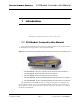
S ECURE CO NSO LE S ERVERS 1 SCS Models Covered in this Manual Introduction Introducing the Logical Solutions Inc. Secure Console Servers 1.1 SCS Models Covered in this Manual All Logical Solutions Secure Console Server (SCS) models covered in this manual are similar in physical appearance, setup and functionality. Figure 1.
Introduction Figure 1.2 SCS160R Secure Console Server, front and rear views The following SCS models are available for International customers, and are shipped with regionally-appropriate AC power cordsets (otherwise similar to the SCS160 / SCS320 / SCS480, respectively). • • Model SCS1601 - 16-Port 1U Secure Console Server, International Model SCS3201 - 32-Port 1U Secure Console Server, International • Model SCS4801 - 48-Port 1U Secure Console Server, International 1.
Software Features S ECURE CO NSO LE S ERVERS Figure 1.3 SCS320 Secure Console Server (32 Ports), front and rear views 1.3 Software Features The SCS is designed with network administrators in mind. No need for special administration tools, training or procedures. You know Linux, we run Linux.
Introduction Figure 1.4 SCS480, 48-Port Secure Console Server, front and rear views The SCS can help you troubleshoot your networking environment. The SCS is a "listening" system that monitors the messages (ASCII data, server error information, etc.) from the serial port of the device to which each Port is connected. The SCS captures the data by writing it to a port buffer, each of which can hold 256K bytes of data.
Technical Specifications S ECURE CO NSO LE S ERVERS 1.
Introduction Figure 1.5 SCS320R, showing front and rear views SCS160 / SCS320 / SCS480 SCS160R / SCS320R Page 14 www.thinklogical.
Intended Application S ECURE CO NSO LE S ERVERS 2 Product Overview Optimize your System Administration and Network Resources 2.1 Intended Application The Logical Solutions Secure Console Servers are used to securely monitor and centrally manage up to 48 of your networking systems (servers, routers, switches, etc.). They do so by monitoring the Console Port of your network center’s devices and systems. Each attached component must have an EIA-232 compatible serial console port.
Product Overview 2.2 System Chassis Each SCS is housed in the rack-mountable metal chassis. Vents are found on both sides of the chassis, and 3-position rack mount brackets are provided and removable. The front panel of the SCS features a two-line backlit LCD display with push buttons. 2.2.1 SCS160 / SCS320 / SCS480 Each SCS chassis has rear-panel connections for 16, 32 or 48 serial ports, one Console port, one Network port, and power. The SCS has a built-in universal AC power supply.
Connecting to the SCS S ECURE CO NSO LE S ERVERS 2.3 Connecting to the SCS All physical connections to the product are made to the rear panel using industrystandard cabling and connectors (purchased separately). All serial connections and network connections use conventional Category 5 cabling having RJ45 jacks. AC Power is connected using an IEC cordset, one of which is provided with each SCS system. Figure 2.
Product Overview 2.3.2 IP Network The SCS network interface is an auto-sensing 10 BaseT/100 BaseTX network connector (equipped with an RJ45 jack with dual LEDs) for use with a conventional TCP/ IP network using standard RJ45 Category 5 cables. A default IP address is coded into the system (10.9.8.7), however the network settings should be configured by your system administrator to be suitable for your site’s requirements and unique equipment. The SCS products are preconfigured for ssh (secure) access.
User Access Control S ECURE CO NSO LE S ERVERS 2.4 User Access Control Access to a Port is controlled on a per-user basis via a user profile, which is stored as a file on the local SCS. This profile is created by the root user using the command ‘adduser’. See Section 8.1.1, adduser, on page 68. 2.4.1 User Sessions Each SCS supports up to 250 simultaneous user sessions. This is possible since a user can generate multiple sessions.
Product Overview For Your Notes SCS160 / SCS320 / SCS480 SCS160R / SCS320R Page 20 www.thinklogical.
Mounting the SCS S ECURE CO NSO LE S ERVERS 3 Installation Place it in your Rack. Connect the Cat5 cables to the Ports. Plug it in. 3.1 Mounting the SCS You may choose to rack mount your SCS unit(s) or place them on a shelf. The front panel display should be visible and front panel buttons need only be accessible for the initial setup of the system. All connections are made to the rear of the chassis. 3.1.
Installation 3.1.2 Front Panel Display and Buttons The front-panel LCD display should be visible and accessible during system setup. It normally shows the current network settings and the date/time. The front panel buttons are only used during setup, or to review existing SCS settings. The LCD display can be customized by the root user. See Section 7.7, Front Panel Display Options, on page 57 for more information. 3.1.
Connections S ECURE CO NSO LE S ERVERS 3.2.3 Connecting to the Network Port Use a conventional fully-pinned Category 5 cable to connect your network connection to the NETWORK jack (RJ45) on the rear of the chassis. The SCS’s network port (auto-selecting 10/100) allows remote access to the attached networking components by the users and the sysadmin functions by the root user.
Installation 3.2.4.1 SCS160R / SCS320R Dual Console Interface The SCS160R / SCS320R has dual Console Ports, with the Console Port 1 pinned as DCE and the Console Port 2 pinned as DTE. The default configuration of these Console Ports has the second Console Port disabled. To use the second Console port, the root user must enable it. The second console port is activated by editing the file /misc/inittab . Refer to Section 6 for other System Commands. 3.2.5 Connect to the Ports Any system (e.g.
Connections S ECURE CO NSO LE S ERVERS 3.2.5.2 Serial Port Pinout Figure 3.
Installation 3.3 SCS160R / SCS320R Power Modules The SCS160R and 320R provide dual AC power inputs which are field-replaceable, which connect to the rear panel of the SCS chassis. Each Power Module has a power entry connection with an IEC-type power connector. The SCS160R and SCS320R have a Power Monitoring display shown on the front panel to indicate if one of the power supplies is not powering the system (either AC power failure, a Module is turned off, or the supply has failed).
S ECURE CO NSO LE S ERVERS SCS160R / SCS320R Power Modules 3.3.1 AC Power Module Replacement The AC Power Modules of the SCS160R and SCS320R may be hot-swapped if necessary by a competent technician. Each slide-in power module is held in place with a single screw and does not need to be removed except for replacement. Figure 3.
Installation Figure 3.5 Replacing an AC Module (Left Module shown partially removed) Note To remove the AC Module, you only need to loosen the one captive screw on the Module. You do not need to remove the chassis from your rack, or remove the cover of the chassis for any reason. The photo above shows the cover removed for clarity only. Insert the replacement Power Module in its place (it will require a slight amount of force to insert), and tighten the screw.
Default Configuration S ECURE CO NSO LE S ERVERS 4 Initial Configuration It’s Pre-Configured. Set your IP Address. Just Add Users. 4.1 Default Configuration Out of the box, the SCS is pre-configured, ready to generate ssh keys, and has an IP address set to a generic default value of 10.9.8.7 / NetMask 255.0.0.0. It is likely that the sysadmin will want to change from this default IP address to your local IP information. The sysadmin will only need to add user information specific to his site.
Initial Configuration 4.2 Initial System Security Concerns The first login will require several steps to fully secure the SCS. When you first connect the SCS and turn it on, the SCS will build the ssh host keys during the first two minutes of system startup. During this time, the front panel LCD bottom line reads 'start sshd', and the console port reads 'Starting sshd'. The system is not dead or locked up, but is generating ssh host keys. The root user should also configure the ntp and the ssh files. 4.
Initial Connection via Network S ECURE CO NSO LE S ERVERS 4.3.3 Route via Windows workstation If using a Linux workstation, ignore this section. If using Windows 9x/2000/XP, you can connect to the SCS using your networked Windows PC and an ssh-capable terminal emulation package. Note If you don’t have an ssh-capable terminal package, try using PuTTY, a freely-distributed package you can download at http://www.chiark.greenend.org.uk/~sgtatham/putty/ .
Initial Configuration Figure 4.2 PuTTY Configuration Screen The first time you connect using ssh, you will get a warning about the ssh authentication keys. Accept the newly-generated keys by choosing ‘yes’. 5. Login to the SCS When connected to the SCS, the ‘login as:’ prompt will appear. You want to log in as root . Press Enter to continue. The ‘password:’ prompt comes up next. Enter root (the default root password) and press Enter.
Front Panel Network Setup S ECURE CO NSO LE S ERVERS When successfully logged in, you will see the command prompt ending with # followed by your cursor. You should change your SCS’s network address as one of the first changes you make. See Section 7.2, Change Network Address, on page 53. 4.4 Front Panel Network Setup If you changed the Network settings via netconfig, you can skip this section. By default, the Front Panel Display and buttons can be used to set the basic network parameters.
Initial Configuration Note Use the ENTER button to ‘continue’ or to ‘accept current setting’, whichever is appropriate at that time. Your front-panel entries must be no longer than 30 seconds apart, or the front panel entry program will time out and discard any of your entries. An asterisk to the far right indicates there is a parameter that has changed from the currently-stored value.
Front Panel Network Setup S ECURE CO NSO LE S ERVERS 4.4.1.2 Program Network When you select the Program Network Settings mode, you step through the parameter entry for Network IP Address, Net Mask and Gateway, and Exit to the previous menu. The Up and Down arrows are used to scroll through the available options. Network IP Address Figure 4.2 SCS Front Panel Display, for Network Programming mode Press Enter to Program Network Settings Press the ENTER button to continue. Figure 4.
Initial Configuration As soon as you change a digit, an asterisk (*) will appear to the right on the top line, indicating that a parameter has changed. Figure 4.5 SCS Front Panel Display, Asterisk indicating a change Edit IP Address 192.168.075.239 * When you have the complete parameter value as it should be, press the ENTER button to complete the entry. The display will show the following: Figure 4.6 SCS Front Panel Display, after editing the IP Address IP Address 192.168.075.
Front Panel Network Setup S ECURE CO NSO LE S ERVERS Figure 4.8 SCS Front Panel Display, editing the Net Mask setting Edit Net Mask 255.200.000.000 * As soon as you change a digit, an asterisk (*) will appear to the right on the top line, indicating that a parameter has changed. Change the Net Mask as desired. Note Ignore any leading 0’s in the display entry. The SCS will adjust for them and will not store the leading zeroes when saving the data.
Initial Configuration Figure 4.11 SCS Front Panel Display, Edit the Gateway setting Edit Gateway 010.001.002.003 Press the Left or Right arrow button to move the cursor to the first digit to be changed. To change a digit, use the Up or Down arrows to change the number. As soon as you change a digit, an asterisk (*) will appear to the right on the top line, indicating that a parameter has changed. Note Ignore any leading 0’s in the display entry.
Front Panel Network Setup S ECURE CO NSO LE S ERVERS Figure 4.14 SCS Front Panel Display, exiting the LCD Mode Exit to Main Menu You are given the choice to Save your changes or to Cancel them. Figure 4.15 SCS Front Panel Display, Save or Cancel Changes Enter = Save Cancel = UP Press 'ENTER' to save your network changed, or press the Up Arrow to discard them.When you are done with your network settings, and have made changes, the system must restart the network daemon.
Initial Configuration For Your Notes SCS160 / SCS320 / SCS480 SCS160R / SCS320R Page 40 www.thinklogical.
SCS Systems are Linux-based S ECURE CO NSO LE S ERVERS 5 System Administration 5.1 SCS Systems are Linux-based The Logical Solutions Secure Console Server products use the GNU/Linux operating system. 5.1.1 Linux General Public License The GNU/Linux source code used in this product has been distributed under a General Public License (GPL) from the Free Software Foundation. You may read about the GNU GPL by reviewing the text version of the GPL, which can be found at http://www.gnu.org/licenses/gpl.txt.
System Administration 5.1.3 SCS System Architecture The SCS software design uses both RAM (volatile) and Compact Flash (non-volatile) memory. Any system changes are maintained in RAM until they are written to the Compact Flash memory. A read-only memory system is used since Compact Flash memory devices have a limited number of read-write cycles. After making administrative changes to the system, the root user must run the save command to write the changes to the non-volatile memory.
Initial Sysadmin Access S ECURE CO NSO LE S ERVERS 5.2.2 Log In as root At the command prompt, type root to access the SCS as the root user. The default password is root. Note The root user should change the default root password (use the passwd command) as soon as possible to prevent undesired SCS system access. You will see the short Hostname (e.g., “scs”) in the root login (#) prompt. Figure 5.
System Administration 5.3 Default Services The following Services are enabled by default: • • network ssh • • syslog cron You may add other features and services, depending on your application. When you first log into the system, you will get a reminder message for configuration: Figure 5.
Default Services S ECURE CO NSO LE S ERVERS 5.3.1.1 Configure the Services When you first install the SCS system, you should configure the default services for your needs. This addresses the network, the date/time, authorizations, and the system hostname. The feature commands described below are discussed in Section 7, System Administration, beginning on page 53. In order to properly configure the basic services, you must: 1.
System Administration For Your Notes SCS160 / SCS320 / SCS480 SCS160R / SCS320R Page 46 www.thinklogical.
System Commands S ECURE CO NSO LE S ERVERS 6 Commands A summary of special SCS Commands 6.1 System Commands The SCS products use Linux command formats, and man pages are available and online for all system commands. The root user can access the following commands to configure the special features of the SCS: COMMAND PU RPOSE C H.
Commands 6.2 save Command The SCS systems will maintain your settings in RAM memory as long as system power is applied and the system remains in a normal operating condition. To permanently store your parameters, the system has a save command. In order to prevent the inadvertent loss of your precious data due to an inadvertent power failure, the root user must use the save command to write the data changes to the non-volatile Compact Flash memory card. This will ensure your data is maintained as desired.
poweroff S ECURE CO NSO LE S ERVERS 6.4 poweroff If you want to turn the system power off (e.g., to move the chassis, etc.) you must first run the poweroff command before turning the power switch off. Note No ‘break’ commands will be sent on the serial Ports during a SCS system poweroff cycle. Your servers will not be adversely affected. poweroff may be manually run at any time, if required. The save command is auto-run as part of the poweroff command.
Commands Refer to the man pages for scp for a description and any command options. sftp Use sftp for a secure file transfer transaction using ssh, between two servers. This process is similar to ftp except that it is encrypted for security. Refer to the man pages for sftp for a description and any command options. ssh The SCS systems use ssh to establish secure connections over your network. The configuration file for ssh is /etc/ssh/sshd_config.
Change Logging Level S ECURE CO NSO LE S ERVERS Note For example, to administer Port 7 you would edit the file rc.serial and would use stty -F /dev/ttyB7. Refer to the man pages for stty for a description and any command options. versions Use versions to see a listing of the release versions of the LSI files in the SCS. 6.6 Change Logging Level The sysadmin may wish to change the logging level of syslog. 1. Login as root 2. Edit the file /etc/syslog.conf ( vi /etc/syslog.conf ) 3.
Commands For Your Notes SCS160 / SCS320 / SCS480 SCS160R / SCS320R Page 52 www.thinklogical.
Security S ECURE CO NSO LE S ERVERS 7 System Administration This section outlines the administration functions and commands, accessed using your Network or the Console port. 7.1 Security The Logical Solutions Secure Console Servers use ssh to provide encryption for a secure network connection. There is only one level of system administration access in the SCS, and that is at the root level. Caution Anyone with the root password has the ability to access all SCS features and functions.
System Administration 7.2.1 Run netconfig After you establish a connection to the SCS using your network, you may want to change the IP address setting of the SCS to the desired address on your network, using netconfig . The netconfig script is a self-prompting program to set up your system’s network information. It supports DHCP/BOOTP setup, or static addressing. Use the space bar to select / deselect a value (e.g., DHCP). Use the arrow keys to move up and down between the entry fields.
Change Network Address S ECURE CO NSO LE S ERVERS Figure 7.1 Example of netconfig fill-in fields When you have filled in the fields, arrow down to the OK button and press Enter to accept your entries. 7.2.2 More Than One Nameserver The netconfig command allows the user to set up one nameserver’s IP address. It is possible to have multiple nameservers, which must be done outside of the netconfig routine. The nameserver data is in the file /etc/resolv.conf.
System Administration 7.3 Change Hostname The SCS includes a command changehostname which allows the root user to change the long hostname of the SCS unit. 1. Log in as root. 2. Type changehostname . The current hostname is displayed, and you are prompted to choose y/n to proceed. 3. If you select y to change, you are prompted to enter the new hostname. Note If you make a mistake in your entry, simply continue (do not attempt to edit); you can reject your bad entry and re-enter the value properly. 4.
Configure Authentications S ECURE CO NSO LE S ERVERS This file already has the various commands in place, but they are commented out. Edit your /etc/module.conf as appropriate. Remove the '# ' from one of the four options lines above, and then reload the NIC driver.
System Administration Figure 7.2 Default ‘Normal’ Front Panel Display, scs.localdomainname Tue Mar 18 15:53:03 2003 The front panel will display system messages (e.g., during reboot or save events) but will return to the ‘normal’ display after these events are done. Note The Edit Mode can be disabled, and the front panel display’s normal display can also be changed. The default setting allows the editing of the IP address information using the front panel buttons.
Network Time Service S ECURE CO NSO LE S ERVERS 7.7.1.3 LINE_1 LINE_1= info allows the Customer to show any data they choose on the upper line of the display. The root user enters a left-justified text line, up to 24 characters, which will be displayed. The upper line of the display is otherwise the SCS’s Hostname. Figure 7.3 LINE_1 Changed in SCS Front Panel Display, 24 characters for Line 1 Tue Mar 18 15:53:03 2003 7.7.1.
System Administration 7.8.1 Configure NTP The file /etc/ntp.conf has many options. We want to define the time servers to use. You need the hostname (or IP address) of the time servers you wish to access. Using your editor, edit the file and add the line: server to the end of the file. For example, let's use the name ts1.mydomain . Your entry is server ts1.mydomain You need the hostname (or IP address) of the time servers you wish to access.
S ECURE CO NSO LE S ERVERS NIS and User Port Permissions 7.9 NIS and User Port Permissions The SCS can use NIS to control user access to the Ports in addition to controlling user access to the SCS itself. This is an extension to the normal NIS capabilities. Some of the NIS files must be installed on your NIS server. The user must create/modify their NIS database to include records containing user port permissions.
System Administration 7.9.3 NIS Port Access The file lsi_port_access contains the port permissions for connect, monitor and clear. It is referenced by a group; you may define any number of groups you need. The following example will illustrate how the group file is constructed.
NIS and User Port Permissions S ECURE CO NSO LE S ERVERS 7.9.4 User Names and Groups The LSI Port User Definition file ( /nis/lsi_port_users) is used to assign a user to a given Port Access group. This file information is found in /usr/doc/nis. The following example will illustrate how it is set up. user name : group name where user name group name a valid SCS user a valid user’s group Example: tomv : pbxgrp billf : itgrp The above example shows two users, tomv and billf.
System Administration 7.9.6 NIS Make file The file Makefile.nis.portAccess is used to create the lsi port database. To build the database, the above files (listed in Section 7.9, NIS and User Port Permissions, on page 61) need to be loaded on the NIS server. The system has been tested on a linux machine running RedHat 8.0. The files were placed in the /var/yp directory. After the make file executed, the lsi database file was placed in the NIS host directory. 7.9.
SNMP S ECURE CO NSO LE S ERVERS mounted, then create the additional directories under the /mnt directory (e.g., /mnt/dir1, /mnt/dir2, /mnt/dir3...). To test the mounting, enter the following: mount -t nfs : Example: mount -t nfs nyc:/usr/local/cvs /mnt/dir2 Note To have this mount happen at startup, you must edit the file /etc/fstab. See the man pages above for details.
System Administration The default file entry is *.notice, with lower level settings (a lower level generates more messages) in *.info . 7.13 Timeouts The SCS system supports timeout on the network port. Refer to the man page for timeout options. Use the commands timeoutd and timeouts. SCS160 / SCS320 / SCS480 SCS160R / SCS320R Page 66 www.thinklogical.
User Setup S ECURE CO NSO LE S ERVERS 8 Administering Users The following commands are used to change settings for Users. You can define as many Users as you wish, up to the memory capacity of the system. The limiting factor when it comes to Users is not the number of users but rather the number of simultaneous sessions invoked by any number of users (250 sessions maximum). 8.1 User Setup Each user account must have a unique name, and each has its own password.
Administering Users There are three permissions in the user config files: ALLOW_CONNECT User can enter interactive mode (file name is /dev/ttyBnnn ). In order to browse a buffer, a user must have connect permissions on that port. ALLOW_MONITOR A user can watch a port (file name is /dev/monitor_portnnn , must be opened in Read-only mode) ALLOW_CLEAR A user can clear a buffer (file name is /proc/port_buffers/nnn ) 8.1.1 adduser SCS Users are identified by a name.
User Setup S ECURE CO NSO LE S ERVERS 8.1.4.1 editbrk Use editbrk to edit the break sequence for a user. The break sequence (user key strokes, default is 'ESC - B') is presented in its ASCII form. 8.1.4.2 editesc Use editesc to edit the escape sequence for a user. The escape sequence (user key strokes, default is 'ESC - A') is presented in its ASCII form.
Administering Users For Your Notes SCS160 / SCS320 / SCS480 SCS160R / SCS320R Page 70 www.thinklogical.
User Accounts S ECURE CO NSO LE S ERVERS 9 User Operations Commands that an End User needs to connect to their Servers through the SCS 9.1 User Accounts The SCS has two types of user accounts: user, and root. The SCS supports multiple user accounts, each having a unique combination of read, write and review privileges to each of the Ports. Each defined user may or may not have the ability to interact with any of the attached servers, in any possible combination. Each user account is password protected.
User Operations 9.2 Port Identities Each Port is numbered (1 through 48) and have default names (port1 through port48, respectively) and may also be given a familiar name by the sysadmin. The Users interact with the servers connected to the ports by entering a command associated with either the port number or port name. 9.3 What Can A User Do Summary: use connect to access a specific server or network device. 9.3.
What Can A User Do S ECURE CO NSO LE S ERVERS To escape from interactive mode, the interactive mode escape sequence must be used. The interactive mode escape sequence is a series of two to ten characters that allow the user to leave interactive mode and return to the system prompt. The default for the interactive mode escape sequence is A (escape key, then uppercase "A"), but the user may change the sequence by using the command editesc. 9.3.
User Operations 9.3.6.1 Edit Escape Sequence The User can edit the Escape command sequence, if necessary. The user only change the escape sequence if it causes problems with the hardware or software used. When logged in, a user can enter editesc to edit or view their preset ‘Escape’ sequence. The escape sequence (user key strokes, default is 'ESC - A') is presented in its ASCII form (x1bA). If the user wishes to keep the existing sequence, they need only to press to keep the existing setting.
Safety Requirements S ECURE CO NSO LE S ERVERS 10 Regulatory & Safety Regulatory Information and Contact Information 10.1 Safety Requirements 10.1.1 Symbols found on the Product Markings and labels on the product follow industry-standard conventions. Regulatory markings found on the products comply with requirements. 10.1.2 Product Serial Number The SCS products have a unique serial number, imprinted on a small silver label that is placed on the bottom of the chassis.
Regulatory & Safety 10.2 Regulatory Compliance The Logical Solutions Inc. SCS products are designed and made in the U.S.A. The SCS products have been tested by a nationally recognized testing laboratory and found to be compliant with the following standards (both domestic USA and many international locations). 10.3 North America These products comply with the following standards: Safety • UL60950 : 2000 • CAN/CSA C22.2 No.
European Union S ECURE CO NSO LE S ERVERS 10.4.
Regulatory & Safety Note This Class A digital apparatus complies with Canadian ICES-003 and has been verified as being compliant within the Class A limits of the FCC Radio Frequency Device Rules (FCC Title 47, Part 15, Subpart B CLASS A), measured to CISPR 22: 1993 limits and methods of measurement of Radio Disturbance Characteristics of Information Technology Equipment. This Class A digital apparatus meets all requirements of the Canadian InterferenceCausing Equipment Regulations.
S ECURE CO NSO LE S ERVERS SCS160R / SCS320R Power Modules 10.7 SCS160R / SCS320R Power Modules The SCS160R and SCS320R systems have hot-swappable AC Power Modules which can be replaced by a competent technician in the field without interrupting service. Each Module is held in place with a single captive screw.
Regulatory & Safety For Your Notes SCS160 / SCS320 / SCS480 SCS160R / SCS320R Page 80 www.thinklogical.
Customer Support S ECURE CO NSO LE S ERVERS 11 How to Contact Logical 11.1 Customer Support Thank You to our Customers for choosing a Logical Solutions product for your application. We appreciate your business and are interested in helping you successfully use our products. Logical is here to help you. To contact Logical Solutions, use the following telephone numbers and internet-based methods.
How to Contact Logical Note Most online documents are stored as Adobe Acrobat “PDF” files. If you do not have the Adobe Acrobat Reader needed to view PDF files, visit www.adobe.com for this free download. 11.1.2 E-mail Logical Solutions is staffed Monday through Friday from 8:30AM to 5:30PM, Eastern Time Zone. We will try to respond to your email inquiries promptly, using the following email addresses for your different needs: info@thinklogical.
Product Support S ECURE CO NSO LE S ERVERS 11.2 Product Support Logical Solutions Inc.’s support personnel are available Monday through Friday from 8:30AM to 5:30PM, Eastern Time Zone. If your application might require assistance at some time outside of our normal business hours, please contact us beforehand and we will do our best to make arrangements to help you with your Logical Solutions products. 11.2.1 Warranty Logical Solutions Inc.
How to Contact Logical For Your Notes SCS160 / SCS320 / SCS480 SCS160R / SCS320R Page 84 www.thinklogical.
Product Support S ECURE CO NSO LE S ERVERS Appendix A File System A.1 Read-Only vs. Read-Write You may choose to interact directly with the SCS’s file system, in which case, you must mount it for read-write access before your changes will be saved to the system’s Compact Flash memory device. It is not necessary to do this, to use the SCS. Caution Regular SCS use does not require changes to Read-Write operation.
How to Contact Logical A.1.2 LSI Directories The following LSI directories are important for the SCS products: /etc /home /var /root /lsi The save command tar’s these directories and stores the tar file in /misc. SCS160 / SCS320 / SCS480 SCS160R / SCS320R Page 86 www.thinklogical.
Product Support S ECURE CO NSO LE S ERVERS Appendix B FAQ A few frequently-asked questions B.1 How do I do this? This section is a collection of tips and hints for various setup items. The root user can change the following features using the following command steps: B.1.1 Change Port Parameters Serial Port settings are modified via the stty command (see man page stty). The serial port settings must be modified in the rc.serial file in order to be permanently changed.
How to Contact Logical B.1.3 View a Buffer You use less, cat, etc.to view a port’s buffer. There are at least two methods: /lsi/ports/buf_ or /proc/port_buffers/ B.1.4 Control the Output of Debugging Messages There is an option to control the output of debugging messages. This is a very handy option to have for sysadmins who are integrating NIS port access. This option allows one method of isolating a problem area during NIS configuration.
Product Support S ECURE CO NSO LE S ERVERS tel (203) 647-8700 Page 89 Product Manual - MAN-000001C
For Your Notes SCS160 / SCS320 / SCS480 SCS160R / SCS320R MAN-000001C - 90 pages www.thinklogical.