
Operations Guide

Intelligent Electronic swing handle – User operations guide
12
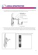
Door Switch Sensor
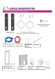
1. The Door Switch Sensor consists of two parts:
● 1.2m cable to 5pin connector with Door switch sensor
● Magnet
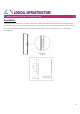
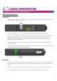
2.
Plug the 5pin connector into the back of the i-Handle
.
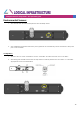
3. Route and attach the 1.2m cable to the inside of the door and attach the switch sensor to the door
using a dual adhesive pad or screws. In most instances the best location is near the top of the door on
the handle side.
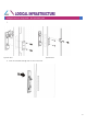
4. Close the door and locate the position on the frame inside the rack that corresponds to the location of
the switch sensor.
5. Open the door and attach the Magnet to the frame in the location identified using a dual adhesive
pad or M3 tapping screws.
6.
The magnet and switch sensor must come into contact when the door is closed for the sensor to
determine door closed status
.
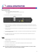
Lock:
1. The Euro profile lock barrel can be replaced with an alternate lock barrel either before or after the
handle is installed.
2. Removing the lock retaining screw.
3. Slide the lock cylinder barrel out of the i-Handle and replace it with the alternate barrel.
4. Re-install the lock retaining screw.
Note: The lock barrels supplied by Logical Infrastructure are designed specifically for use with the i-Handle.
Other lock barrels may result in reduced i-Handle functionality.