
Operations Guide


Intelligent Electronic swing handle +POE Bridge SBIP01 – User operations guide
13
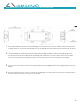
Logical
Infrastructure
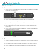
Network connection:
Front Door
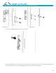
1. Connect the i-Handle Comms Cable 4 pin to RJ45 150mm cable to the iHandle and attach the Blue
Network Cable to the RJ45 connector.
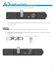
2. Connect the RJ45 coupler and Blue Network Extension Cable to the Blue Network Cable.
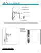
3. Route and fix the network cable using cable ties and adhesive pads. Ensure the network cable has
slack on the hinge side of the door so that it does not get pinched. Ensure the RJ45 coupler is
positioned near the hinge to enable the network cable to be disconnected and allow the easy
removal of the door (if required).
4. Install the Cable Protect Cover by placing it over the back of the i-Handle and sliding the Cable
Protect Cover up.
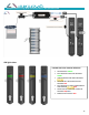
5. Connect the blue Network cable to the RJ45 Port labelled port 1 or 2 on the POE Bridge SBIP01. The i-
Handle LED light should now be illuminated.
Rear Door
1. The network connection for the rear door is the same as the front door except the RJ45 coupler and
Blue Network Extension Cable are not used and the Red Network Cable is used instead of the blue
cable.
2. Ensure the network cable has slack on the hinge side of the door so that it does not get pinched.
3. Connect the RED Network cable to the RJ45 Port labelled port 1 or 2 on the POE Bridge SBIP01
4.