LK1800 series Programmable QWERTY Keyboard 120 key programmable alphanumeric keyboard USER MANUAL
NOTICE The manufacturer of the POS programmable keyboard makes no representations or warranties, either expressed or implied, by or with respect to anything in this manual, and shall not be liable for any implied warranties of fitness for a particular purpose or for any indirect, special or consequential damages. Information in this document is subject to change without notice and does not represent a commitment on the part of the manufacturer. FCC NOTICE This device complies with Part 15 of FCC Rules.
TABLE OF CONTENTS FEATURES…………………………………………………………............. 4 CARTON CONTENTS……………………………………………………... 5 MODELS……………………………………………………………………... 5 HARDWARE CONNECTIONS……………………………………………. 6 FUNCTIONALTEST………………………………………………………… 7 UTILITY DISK CONTENTS………………………………………………... 8 INSTALLINGTHE LCI KEYBOARD PROGRAMMING UTILITY………. 9 MENU COMMANDS……………………………………………………….. 10 PROGRAMMING THE LK1800 KEYBOARD........................................ 10 EDITING KEY DEFINITIONS……………………………........................
FEATURES • 132 key, programmable alphanumeric keyboard • Optional integrated credit card reader • All 132 keys are programmable; 44 keys are relegendable with transparent key caps • Multiple layers of key definitions and multiple shift levels • Keylock switch for layer selection • Programmed with a powerful Windows-based programming utility software • Create program layout for multiple keyboards – programming utility saves templates as data files • Program up to 1800 characters or codes • P
CARTON CONTENTS LK1800 1. 2. 3. 4. 5. Programmable Keyboard LK1800 series Computer interface cable - RJ11 to male PS/2 mouse and keyboard interface (For LK1800U models: RJ45 to USB Type A interface) Programming Utility software and User’s Manual disk Legend label sheet 2 keylock keys MODELS LK1800 LK1800U LK1800M LK1800MU - LK1800 with PS2 interface LK1800 with USB interface LK1800 with integrated MSR, PS2 interface LK1800 with integrated MSR, USB interface 5 LK1800 User Manual Rev.
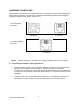
HARDWARE CONNECTIONS The LK1800 can be connected to a PS/2 computer, or computer terminal. The following diagram shows how the keyboard connects to the computer and standard keyboard or other keyboard peripheral (magnetic stripe reader, scanner, etc.). LK1800/LK1800M back panel To peripheral To Computer LK1800U/LK1800MU back panel To Computer NOTE: Before making any connections it is always advisable to turn off the computer. A. Connecting the LK1800 to a PC keyboard port: 1.
FUNCTIONAL TEST For testing purposes, your LK1800 keyboard was pre-programmed with a key definition template called LK1800-L1.tpl. The following simple steps will verify that the keyboard is in good working condition: 1. Follow the Hardware Connections directions on page 6 in this manual to connect the LK1800 to your computer. 2. Turn on the computer. 3. Under Windows, open Notepad or any text editing software. Press keys on the keyboard one by one to verify that programmed key definitions are activated.
UTILITY DISK CONTENTS All LK1800 keyboards come with a utility software disk. This disk contains several important files: SETUP.EXE LK1800-L1.TPL LK1800-L2.TPL LK1800 User Manual This utility will install the keyboard programming utility on your computer. Use this utility with the keyboard attached. These templates were pre-programmed into the keyboard and match the legend shown below.
INSTALLING THE LCI KEYBOARD PROGRAMMING UTILITY 1. Make sure the LK1800 is attached to the computer. 2. Double click the SETUP.EXE file on the utility diskette. 3. Select the destination folder if necessary and click “Install” to start the installation process. Skip any warning messages by clicking “Yes” or “Continue”. 4. When installation is completed, reboot the computer. 5. Utility can be started through Windows by clicking on Start→Programs→LCI Keyboard Utility 6.
MENU COMMANDS [Template] [New] [Load] [Save] [Save As] [Load Default] [Import Text Data] [Export Text Data] [Exit] [Keyboard] [Key Edit] [Clear Current Key] [Set ASCII Mode] [Set ScanCode Mode] [Insert Caps Code] [Insert Delay Time] [Enter Level Separator] [Enter Shift Level code] [Enter ASCII Code] [Switch ASCII Display mode] [Select Scan Code] [Configuration] [Read From KB] [Write Into KB] [Config KB Properties] [Config MR Properties] [Testing] [Keyboard Output] Clear all key definitions.
PROGRAMMING THE KEYBOARD 1. Connecting the Keyboard For PS/2 versions: Connect the LK1800 to the PC with the special interface cable provided. Plug the standard PC keyboard to the female PS/2 connector on the interface cable and the male PS/2 connector to the computer. For USB versions: Connect the LK1800 to any USB port on the computer. 2.
EDITING KEY DEFINITIONS 1. Selecting Keys to Edit Use Shift Key and the Arrows Keys on the standard keyboard to select the key for editing. Hold down the shift key and hit the arrow keys until the key to be edited is being highlighted. 2. Checking Key Definitions The current key definition is shown on the single line “Key Content” text box below the keyboard layout. 3. Selecting Programming Modes Programming mode is selectable for each individual key.
• • • • For special function keys, use and to enter their scan code in this mode. For example, to program into the key position, hit first, followed by . To program , hit twice. Since the following 4 keys are used by Windows, we cannot use + to program these keys: , , , . These keys have to be programmed in ASCII mode by entering the key token names.
o • [ShiftLevel*] Multi-shift-level function key definition for different shift levels (* is from 1 to 9). To define a Multi-shift-level function key, click icon and enter the level number. on the Decimal equivalent numeric values for ASCII codes (only 1 to 240 icon on the tool allowed) can be entered directly by clicking on the bar or Key Edit→Enter ASCII Code on the menu bar. After code entry, the ASCII code will be shown as a normal character or as blocks if the code is a non-displayable character.
[ShiftLevel2] key and then press the multi-definition key will send out Level 2 definition, and so on. B. Inter-string Delay • A delay time up to 100 seconds can be inserted between key stroke outputs by clicking on the icon on the tool bar or Key Edit→Insert Delay Time on the menu bar. For example inserting [Delay2] will cause keyboard to pause 2 seconds before sending out subsequent output.
MODIFYING PROPERTIES OF THE KEYBOARD After key definitions are finished, click on the item Configuration→Config KB Properties on the menu bar or click on the “Modify Properties” icon on the toolbar to set or change programmable keyboard features. Config OPOS/JPOS • You may configure the keyboard according to which standard, OPOS/JPOS, your POS application is running. Send break-code for scan-code mode key • Enables the transmission of break codes for each scan codes programmed into the keyboard.
DELIMITED TEXT TEMPLATE FILE The new programmable keyboard utility can import and export a delimited text file directly. The text file may have two columns and as many rows as number of keys (See the example .TXT file in the utility diskette). Columns are delimited by commas and rows are delimited by . The first column is key’s name that will appear on the utility’s key layout screen. These names can be also changed. The second column is key’s definition.
KEY LABEL COLOR To identify the status of a key during template editing, the key label is displayed in three different colors. • Black - The key is blank with no definition. • Blue - When a template is loaded from file or read from keyboard, all keys that are not blank will be displayed in blue. • Green - When a key is modified after a template load or keyboard read, it will be changed to green to identify that this key has been changed from the original template.
In this example of the LK1800 template, the F33 key is a defined key and is indicated by the color blue. In this example of the LK1800 template, the F33 key is a modified key and is indicated by the color green. 19 LK1800 User Manual Rev.
PROGRAMMING EXAMPLES 1. Special Features To program key sequence then , the key need to be released before pressing . Otherwise, the definition will be interpreted as , . • [Ctrl][A][0F0][Ctrl][F9] 2. Multi-Shift-Level Function This function programs a key that contains several levels of definitions such as “Small Coke”, “Medium Coke”, “Large Coke”. When pressing this key, the actual output will be any of the 3 strings. We may call this a multi-definition key.
TOKEN NAMES FOR SPECIAL FUNCTION KEYS There are no ASCII codes for some function keys. They have to be programmed with Scan Codes. In key definitions, the following symbols represent their scan codes. The token name symbols are case sensitive. They have to be entered exactly as shown below.
[Alt+PrintScreen] [PAD0] [PAD1] [PAD2] [PAD3] [PAD4] [PAD5] [PAD6] [PAD7] [PAD8] [PAD9] [PAD+] [PAD-] [PAD*] [PAD/] [PAD.
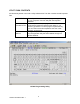
EDITING MSR PARAMETERS (for keyboards equipped with optional MSR) Before editing the parameters, please refer to the user manual of the Point-of-Sale software or credit card verification software to find out what are the requirements on the output format. To configure the MSR from the KBWN.exe utility, click the Configure MR icon. 23 LK1800 User Manual Rev.
1. Edit the keyboard programming template; or load a template from a file; or read the template from the keyboard. In the programming utility main menu, click Configuration on the menu bar and then click on [Edit MR Data]. You can also click the “MR data edit” icon on the tool bar. The MSR parameter edit dialog box will be displayed. 2.
Enable LRC: enable LRC output for each track. If enabled, LRC will be sent as 2 hex characters. Hex values A to F (10 to 15) are represented by characters : ; < - > and ? respectively. 7. Enable Start Sentinel: enable individual track "start sentinel" output. Enable Separator: enable individual track "field separator" output. Enable End Sentinel: enable individual track "end sentinel" output. 8. Track Prefix: maximum 8 characters, sent before start sentinel of each track.
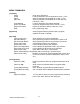
SPECIFICATIONS 26 LK1800 User Manual Rev.