
Operation Manual


Iris Rev. 08 – 2009
English
19
ALWAYS DISCONNECT THE BATTERY PRIOR TO INSTALLATION.
• The chain counter must be positioned so that the display will be easy to read. It should not be
exposed to direct sunlight.
• The rear part of the instrument must be protected from contact with water or moisture.
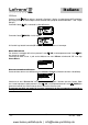
• The instrument may be fastened to dashboards of any thickness. The screws used for clamping
must be of the self-threaded kind and with a diameter of 3.5 mm (~9/64”) and a maximum
length of 10 mm plus the thickness of the dashboard.
• In the part to the rear of the dashboard there must be minimum clearance of 35 mm (1” 3/8) and
there must also be adequate access to perform installation and maintenance work.
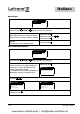
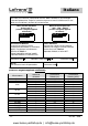
• On the dashboard make a hole with a diameter of 30 mm (~ 1” 3/16), as indicated, and 4 holes
with diameters of 4 mm (~5/32”) for the chain counter clamping screws. Use cutting nippers to
cut the three pins on the back of the instrument, position the chain counter and fasten it to the
dashboard by tightening the four screws. If the dashboard already has a hole with a 54 mm
(2”1/8) diameter, it is not necessary to cut the pins on the back.
• The seal must be positioned between the chain counter and the dashboard.
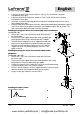
For instructions on making electrical connections, see the attached diagram. The wires must have a
minimum cross section size of 1.5 mm².
• Install a 4 A (ampere) fast safety fuse on the + wire of the battery. Do not use the voltage
generated by the engine battery set to provide power.
• The instrument complies with EMC standards (EN55022) and must be positioned at a distance
of:
− 30 cm (~1 Ft) from the compass;
− 50 cm (~1.5 Ft) from radio equipment;
− 2 metres (~6.5 Ft) from radio transmitter equipment;
− 2 metres (~6.5 Ft) from the radar beam.
www.busse-yachtshop.de | info@busse-yachtshop.de