
Instruction Manual
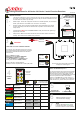

+ Positive 12/24 Volt supply
- Negative 0 Volts
F1, F2, F3 & F4 Outputs to F1 through F4
M Master Output
ST STOP, when grounded shuts down the receiver
Vs- Vs+ 12/24 Volt supply for control circuits (Used when link is broken to allow
switching of DC Voltages outside normal operating limits)
ANT Blade connector for internal antenna
SMA Aerial connection for external antenna (internal antenna must be removed)
LK1 Master Selection by jumper (AP = Parallel, AM = Continuous)
LK2 RS232 for programming
LK3 RS232 for interface with other RS232 modules
LK4 Connected when using parallel master, connects safety circuit
Make connections into plugs supplied but not shown.
+ RED
- BLACK
F1 GREEN
F2 YELLOW
F3 BROWN
F4 BLUE
M WHITE
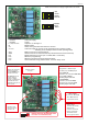
LED marked “5V”
Indicates power
supply for control
circuits is OK
LED’s marked
“F1 - F2 - F3 - F4 and M”
When ON indicate an
output to that function
LED marked “FAULT”
Indicates an overload is
present; the System
cannot be RESET until
overload is removed.
This LED blinks for 20
seconds when the
Receiver is initially
powered. A replacement
Transmitter has to be
registered during this 20
second period.
LED marked “SET”
Indicates system
is active
MASTER OUTPUT
Configuration of Master Output
(not 9X00) is by the BLUE jumper.
either PARALLEL
Activated by any Transmitter FUNCTION
but not STOP or RESET
Connect jumper across A-P
or CONTINUOUS
activated by Transmitter RESET
de-activated by Transmitter STOP
Connect jumper across A-M
JUMPER (RED) MUST BE REMOVED WHEN
LK1 IS SET TO CONTINUOUS (A-M)
LK4
VOLTAGE
Working Range
12 Volts to 36 Volts DC
Absolute Limit
8 Volts to 40 Volts DC
Note 42 Volt System
48 Volt Max Limit is
currently Special Order
9004RX.01E