
User guide

in
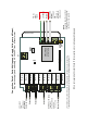
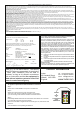
F1
out
in
F2
out
in
F3
out
in
F4
out
in
M
out
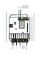
F1 Safety
F1 Switch
F2 Safety
F2 Switch
F3 Safety
F3 Switch
F4 Safety
F4 Switch
M Safety
M Switch
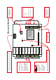
Power Supply
90 - 264 VAC
for control circuits
ST -
E
L
N
C
N
S
N
S
N
S
LK1
LK2
RS232
ANT
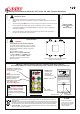
Radio Module
Internal Aerial
glue
SMA connector for
External Aerial Antenna
Part No. 9861, 9862,
9863 or 9869
Supply 90 to 264 VAC
E = Earth
L = Live
N = Neutral (control circuit)
C
N = Neutral (switch circuit)
S
Standard (Internal) Antenna
connection
Receiver Detail
STOP and - (5 Volt circuit), when connected together
will cause the Receiver to power down.
RS232 connection
for programming and
special features
LK1, when bridged
causes the Master
Output to be
Parallel
LK2, when bridged
causes the Master
Output to be
Continuous
POWER DOWN RECEIVER BEFORE MAKING CHANGES
Outputs sockets
F1& F2, F3, F4, & Master.
in = common live
out = load
Each output is designed
to handle 10 Amps Max,
current draw in excess
of this will damage the
Receiver.