
Service Manual

2 Maintenance
Service Manual
32
Oiled bearing circulators
1. The circulator shipped with the Knight wall mount boiler
is water-lubricated. No oiling is required.
2. Check other circulators in the system. Oil any circulators
requiring oil, following circulator manufacturer’s
instructions. Over-oiling will damage the circulator.
3. Replace the boiler front access cover.
The boiler contains ceramic fiber materials.
Use care when handling these materials per
instructions in the Service Manual. Failure
to comply could result in severe personal
injury.
WARNING
5. Remove the condensate trap from the bottom of the
boiler. Place a bucket underneath the condensate fitting
attached to the heat exchanger.
6. Use a vacuum cleaner to remove any accumulation on the
boiler heating surfaces. Do not use any solvent.
7. Using a clean cloth dampened with warm water, wipe out
the combustion chamber. Rinse out debris with a low
pressure water supply.
8. Allow the heat exchanger to thoroughly dry.
9. Perform start-up and check-out procedures in the Check
Flame and Combustion - Section 10 - Startup of the
Knight Wall Mount Installation and Operation Manual.
10. Replace the burner, access cover and condensate trap.
Restore boiler to operation.
* Do NOT use a metal brush.
CAUTION
Test low water flow conditions
NOTICE
This test is to be carried out once the
Knight wall mount boiler is completely
piped in with adequate gas and water
flow. Once the test is completed, ensure
that the isolation valve is opened up to
allow full water flow.
Test procedure
1. Set the [SH1 SETPOINT:] set point to the max user set
point (reference Section 10 of the Knight Wall Mount
Installation and Operation Manual). Max user set point
will allow the boiler to operate without reaching this set
point. The boiler will require a load large enough to
dissipate a large portion of the heat it is generating.
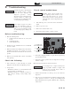
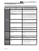
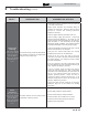
2. Simulate a call for heat by placing a jumper wire across
the enable contacts #19 and 20 on the low voltage
terminal strip (FIG. 2-3).
2. Allow time for the boiler to cool to room temperature if it
has been firing.
3. Remove the nuts securing the heat exchanger access cover
to the heat exchanger and set aside.
4. Remove the heat exchanger access cover and burner.
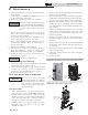
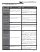
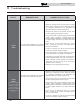
Figure 2-4 Adjust outlet isolation valve
3. Allow the unit to progress through its normal diagnostics
and pre-purge programming.
4. Allow the unit to fire and operate until the temperatures
stabilize. This occurs when the inlet and outlet temperatures
are rising together and the Delta T ( T) is maintained.
5. When the unit stabilizes, begin to slowly shut off the
isolation valve on the outlet piping of the boiler (see FIG.
2-4). This will begin to restrict the flow and simulate a low
flow condition.
6. While slowly shutting off the isolation valve, refer to the
Status Screen to watch the behavior of the boiler. This
screen allows you to monitor the inlet temperature, outlet
temperature, and T.
7. When the T reaches 55˚F, the control will attempt to
modulate the firing rate down to protect it from low flow
conditions.
8. When the T reaches 60°F, the control module will turn
off the burner. If the control module shuts down, the test
was successful.
9. Disconnect the jumper wire from the low voltage terminal
strip connected in Step 2.
10. Completely open the isolation valve on the outlet piping
of the boiler.
11. Resume operation.
A
DJUST OUTLET
ISOLATION VALVE
ONLY
IMG00656
Figure 2-3 Low voltage terminal strip and enable contacts
ENABLE
CONTACTS
LOW VOLTAGE
CONNECTION
BOARD
IMG00164