
Install Instructions


55
8 Field wiring (continued)
Outdoor temperature sensor
In accordance with the United States Energy Policy and
Conservation Act, this boiler is equipped with outdoor air
reset, a feature that saves energy by reducing boiler water
temperature as heating load decreases. To use this feature, the
outdoor air sensor provided with the boiler must be properly
installed.
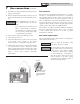
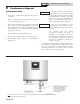
1. Mount the sensor on an exterior wall, shielded from
direct sunlight or flow of heat or cooling from other
sources.
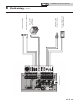
2. Route sensor wires through a designated wiring hole in
the bottom front right side of the boiler (see FIG. 8-3).
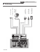
3. Connect outdoor temperature sensor (FIG.'S 8-4 and 8-5)
to the outdoor sensor terminals on the connection board
to enable outdoor reset operation of the Noble Fire Tube.
Air handler contacts (Combi Only)
A set of un-powered contacts are available on the low voltage
connection board (FIG. 8-5) that can be used to turn off the
fan on an air handler when the diverter valve is in the DHW
position and therefore not providing hot water to the space
heating system. These contacts are normally open and will
close when the diverter valve is in the space heat position.
System supply sensor
1. By installing the system supply sensor as shown in the
Hydronic Piping section of this manual, the temperature of
the primary supply can be controlled. The boiler control
automatically detects the presence of this sensor, and
controls the boiler firing rate to maintain the system supply
temperature to the set point.
2. The 100170581 sensor provided with the boiler must be
used for the system sensor.
3. Connect the system supply sensor to these terminals (FIG.'s
8-4 and 8-5).
Do not install the system supply sensor into
the system return.
⚠ CAUTION
Thermostat (field supplied)
1. Connect the room thermostat or end switch (isolated
contact only) to the room thermostat as shown in FIG.'s
8-4 and 8-5.
2. Install the thermostat on the inside wall, away from
influences of drafts, hot or cold water pipes, lighting
fixtures, televisions, sunlight or fireplaces.
3. Thermostat anticipator (if applicable):
a. If connected directly to boiler, set for 0.1 amps.
b. If connected to relays or other devices, set to match
total electrical power requirements of connected
devices. See device manufacturers’ specifications
and thermostat instructions for details.
Wiring of the cascade
When wiring the boilers for Cascade operation, select one boiler
as the Leader boiler. The remaining boilers will be designated as
Members.
Connect the system supply sensor and outdoor air sensor (if
used) to the Leader boiler. For the Cascade system to work
properly the system supply sensor must be installed. The
location of the system supply sensor should be downstream
of the boiler connections in the main system loop. The system
supply sensor should be wired to the Low Voltage Connection
Board at the terminals marked for the system sensor (see FIG.'s
8-4 and 8-5). The Leader control will use the water temperature
at the system supply sensor to control the operation of the
Cascade.
Installation & Service Manual
FIRE TUBE
™
Auxiliary limit switch
A field supplied auxiliary limit switch can be used for the gas
pressure switch. When installing the auxiliary limit switch,
please follow the kit instructions provided with the switch and
then proceed as follows:
1. If the auxiliary switch is mounted to the exterior of the
boiler, run the wires through a knockout in the bottom
front right side of the boiler. If the auxiliary limit switch
is mounted on the interior of the boiler, route the wires to
the connection board.
2. Once the wires are inside the boiler and near the
connection board, connect the wires to the auxiliary limit
switch terminals.