
Install Instructions


67
10 Start-up (continued)
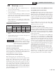
Table 10A Flue Products Chart
6. Once the combustion analysis is complete, exit Service
Mode.
7. Turn the main power off to the boiler and replace the
plug into the vent adapter.
8. Place the boiler back into normal operation.
You must replace the flue gas plug on
the universal adapter to prevent flue gas
spillage into the room. Failure to comply
could result in severe personal injury,
death, or substantial property damage.
WARNING
Goal
Natural Gas Propane
CO
2
O
2
CO
2
O
2
Range 8.5% - 10.5% 2.3% - 5.7% 10.0% - 11% 4.1% - 5.6%
Target 9.0% 4.9% 10.5% 4.9%
Installation & Service Manual
3. Press the ► and ▼ buttons (simultaneously) for 5
seconds to enter Service Mode.
4. Insert the probe from a combustion analyzer into the hole
on the vent adapter.
5. Once the boiler has modulated up to full fire, measure the
combustion. The values should be in the range listed in
Table 10A below. The CO levels should be less than 150
ppm for a properly installed unit.
If the combustion is not within the specified range,
reference Section 13 - Troubleshooting for possible causes
and corrective actions.
Set space heating operation
Determine controlling sensor
For space heating systems, the temperature control can be
based on the outlet or if installed, the system supply sensor
(factory supplied). The control will automatically switch to the
system supply sensor once it is connected.
Verify space heat circulator operation
Note: Diverter valve used on Combi models only.
The Space Heating Mode controls the boiler pump and the
diverter valve. When the boiler control receives a space
heating call for heat and the boiler is not heating a DHW
(Domestic Hot Water) call, and the set point is not met, it
turns on the boiler pump and places the diverter valve in the
space heating position. After the space heating call for heat
ends, the boiler pump continues to run for a short period of
time. This pump delay is factory set to 30 seconds. After this
pump delay, the pump is turned off and the diverter valve is
placed into the DHW position.
Set domestic hot water (DHW) operation
Verify DHW operation (Combi Only)
The DHW Heating Mode controls the boiler pump and
the diverter valve. When the boiler control receives a
DHW call for heat from the DHW flow switch, it turns on
the boiler pump and puts the diverter valve in the DHW
position to route boiler water through the brazed plate heat
exchanger. During the call, the boiler control will modulate
to maintain the DHW outlet temperature to the DHW set
point.
After the DHW call for heat ends, the boiler pump
continues to run for a short period of time. This pump
delay is factory set to 30 seconds.
Verify DHW mode (Boiler Only)
There are two (2) modes of operation for DHW. In Normal
Mode, when a DHW demand begins, the control will start
the DHW pump, turn off the boiler pump (if running),
and modulate to bring the outlet temperature to the DHW
boiler set point. The maximum firing rate may be limited
in this mode if desired.
In Zone Mode it is assumed that the indirect DHW tank
is piped as a zone on the primary loop. When a DHW
demand begins, the control will turn on the DHW pump
output, and raise the system temperature set point to the
DHW boiler set point (if higher). The boiler pump will
be turned on. The system pump may be forced on, forced
off, or not changed, depending on the System Pump Mode
selected. In this mode, any low temperature zones (such as
radiant heating) may need additional controls to limit the
water temperature sent to those zones.
Set DHW boiler target temperature (Boiler Only)
When in the DHW Mode, the control will modulate to
maintain the boiler outlet temperature or system supply
temperature to a set point. This set point is set at the
factory to 180°F. If a different set point is desired, the
appropriate parameter in the control must be changed.
FIRE TUBE
™