00332295_2000589039_Rev B User’s Information Manual Models: 400 - 1000 Series 100 & 101 ⚠ WARNING This manual must only be used by a qualified heating installer / service technician. Read all instructions, including this manual and the Knight XL Service Manual, before installing. Perform steps in the order given. Failure to comply could result in severe personal injury, death, or substantial property damage. Save this manual for future reference.
Contents HAZARD DEFINITIONS................................................... 2 PLEASE READ BEFORE PROCEEDING ...................... 3 1. PREVENT COMBUSTION AIR CONTAMINATION . 4 2. MAINTENANCE SCHEDULE ..................................... 5 Maintenance Procedures ................................................... 6 Boiler Must Be Serviced and Maintained .................... 6 Check Boiler Area ......................................................... 6 Check Pressure Temperature Gauge...................
User’s Information Manual Please read before proceeding NOTICE NOTICE The Knight XL Installation and Operation Manual along with the Knight XL Service Manual are for use only by a qualified heating installer/service technician. Refer only to this User’s Information Manual for your reference. Improper installation, adjustment, alteration, service or maintenance can cause property damage, personal injury (exposure to hazardous materials) or loss of life.
User’s Information Manual 1 Prevent combustion air contamination ⚠WARNING ⚠WARNING If the boiler combustion air inlet is located in any area likely to cause contamination, or if products which would contaminate the air cannot be removed, you must have the combustion air and vent re-piped and terminated to another location. Contaminated combustion air will damage the boiler, resulting in possible severe personal injury, death, or substantial property damage.
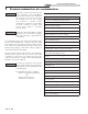
User’s Information Manual 2 Maintenance schedule Service technician (see the Knight XL Service Manual) Owner maintenance (see pages 6 - 8 for detailed instructions) General: • Address reported problems • Inspect interior; clean and vacuum if necessary; • Check boiler area Daily • Clean condensate trap and fill with fresh water • Check pressure/temperature gauge • Check for leaks (water, gas, flue, condensate) ANNUAL START-UP • Verify flue and air lines in good condition and sealed tight • Check
User’s Information Manual 2 Maintenance schedule Maintenance procedures Read the list of potential materials listed in Table 1A on page 4 of this manual. If any of these products are in the room from which the boiler takes its combustion air, they must be removed immediately or the boiler combustion air (and vent termination) must be relocated to another area.
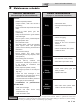
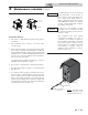
User’s Information Manual 2 Maintenance schedule (continued) Figure 2-1 Condensate Trap NOTICE Use materials approved by the authority having jurisdiction. In the absence of other authority, PVC and CPVC pipe must comply with ASTM D1785 or D2845. Cement and primer must comply with ASME D2564 or F493. For Canada use CSA or ULC certified PVC or CPVC pipe, fittings, and cement.
User’s Information Manual 2 Maintenance schedule Test low water cutoff (if installed) 1. If the system is equipped with a low water cutoff, test the low water cutoff periodically during the heating season, following the low water cutoff manufacturer’s instructions. Operate relief valve 1. ⚠WARNING Reset button (low water cutoff) 1. Testing the low water cutoff shuts the unit off. Press the RESET button on the low water cutoff to turn the unit back on. Check boiler piping (gas and water) 1. 2.
User’s Information Manual 3 Operating instructions FOR YOUR SAFETY READ BEFORE OPERATING WARNING: If you do not follow these instructions exactly, a fire or explosion may result causing property damage, personal injury, or loss of life. A. This appliance does not have a pilot. It is equipped with an ignition device which automatically lights the burner. Do not try to light the burner by hand. B. BEFORE OPERATING smell all around the appliance area for gas.
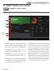
User’s Information Manual 4 SMART TOUCH control module Knight XL control module Use the control panel (FIG. 4-1) to set temperatures, operating conditions, and monitor boiler operation. Figure 4-1 Control Panel HOME VIEW SETUP INFORMATION SETTINGS • The Status Section is located on the top left of the screen and displays how the unit is currently running (i.e.
User’s Information Manual Notes 11
Revision Notes: Revision A (PCP #3000042117 / CN #500030025) initial release. Revision B (PCP #3000042688 / CN # 500030426) reflects an update from SMART TOUCH to SMART TOUCH.