
Install Instructions


63
11 Start-up (continued)
Check fl ame and combustion (continued)
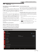
4. Navigate to the Setup Screen from the Home Screen
by pressing the SETUP button along the le side of the
screen. Enter the installer password.
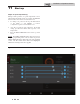
5. Select the Service Maintenance Screen. e tabs will
scroll (up and down) to reveal more options. See
the Knight XL Service Manual for more detailed
information.
6. Insert the probe from a combustion analyzer into the
hole le by the removal of the ue temperature sensor.
7. Once the boiler has modulated up to full re, measure
the combustion. e values should be in the range
listed in Table 11B below. e CO levels shall be less
than 150 ppm for a properly installed unit.
If the combustion is not within the speci ed range,
reference the Troubleshooting Section of the Knight
XL Service Manual for possible causes and corrective
actions.
Set space heating operation
Determine controlling sensor
For space heating systems, the temperature control can be
based on one of three sensors; the inlet, outlet, or system
supply sensor. e SMART TOUCH control is programmed
at the factory to control the temperature of the outlet
sensor. e control will automatically switch to the system
supply sensor once it is connected. If it is desired to base
the temperature control on the inlet sensor, the appropriate
parameter must be changed in the control. See the Knight XL
Service Manual for a detailed explanation of this procedure.
Verify space heat circulator mode
e Space Heating Mode controls both the system pump
(if connected), and the boiler pump. When the SMART
TOUCH control receives a space heating call for heat, it
turns on the system pump. If the boiler is not heating an
indirect DHW (Domestic Hot Water) tank, and the set
point is not met, it also turns on the boiler pump. A er the
space heating call for heat ends, the system pump continues
to run for a short period of time. e system pump can be
programmed to run continuously, except during outdoor
shutdown. If the boiler pump was running, it continues to
run for a short period of time as well. ese pump delays are
factory set to 30 seconds. If di erent delays are desired, the
appropriate parameters in the control must be changed. See
the Knight XL Service Manual for a detailed explanation of
this procedure.
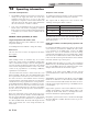
Table 11B Flue Products Chart
8. Once the combustion analysis is complete, test the
safety shuto device by turning the manual shuto
valve to the OFF position and ensuring that the boiler
shuts down and registers an alarm. Turn the manual
shuto switch to the ON position and reset the control.
9. Turn the main power o to the boiler and replace the
ue temperature sensor into the ue pipe connection.
10. Place the boiler back into normal operation.
You must replace the flue gas
temperature sensor to prevent ue gas
spillage into the room. Failure to comply
could result in severe personal injury,
death, or substantial property damage.
⚠ WARNING
Natural Gas Propane
CO
2
O
2
CO
2
O
2
8.4% - 9.4% 4.8% - 6.5% 9.4% - 10.4% 5.4% - 6.9%
Installation & Operation Manual