
Install Instructions


50
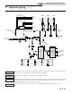
8 Gas connections
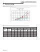
Table 8A Natural Gas Pipe Size Chart
e gas piping must be sized for the proper ow and length of
pipe, to avoid excessive pressure drop. Both the gas meter and
the gas regulator must be properly sized for the total gas load.
If you experience a pressure drop greater than 1 inch w.c.
(249 Pa), the meter, regulator, or gas line is undersized or in
need of service. Perform the steps below when checking inlet
gas supply:
1. Turn the main power switch to the “OFF” position.
2. Shut o gas supply at the manual gas valve in the gas
piping to the appliance.
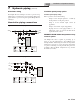
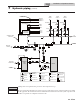
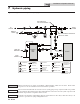
3. On Models 400 - 500 loosen the set screw one (1) full turn
from inside the pressure tap on top of the gas valve. On
Models 650 - 1000 remove the 1/8" (3 mm) pipe plug on
the inlet ange to the valve and install a suitable 1/8" (3
mm) tting ( eld supplied) for the manometer tubing.
Place the tubing of the manometer over the tap once the
set screw is loosened or the 1/8" (3 mm) tting is installed
(depending on model) as shown in FIG.’s 8-4 thru 8-5.
4. Slowly turn on the gas supply at the eld installed
manual gas valve.
5. Turn the power switch to the “ON” position.
6. Adjust the temperature set point on the display of the
SMART TOUCH control module to call for heat.
7. Observe the gas supply pressure as the burner res at
100% of rated input. Percent of burner input will be
displayed on the display.
8. Ensure inlet pressure is within speci ed range.
Minimum and maximum gas supply pressures are
speci ed in this section of the manual.
9. If gas supply pressure is within normal range and no
adjustments are needed, proceed on to Step 11.
10. If the gas pressure is out of range, contact the gas utility,
gas supplier, quali ed installer or service agency to
determine the necessary steps to provide proper gas
pressure to the control.
11. Turn the power switch to the “OFF” position.
12. Shut o the gas supply at the manual gas valve in the gas
piping to the appliance.
13. Remove the manometer from the pressure tap on top of
the gas valve. On Models 400 - 500 re-tighten the set
screw inside the pressure tap. On Models 650 - 1000
remove the 1/8" (3 mm) eld supplied tting and
reinstall the pipe plug removed in Step 3.
Check inlet gas supply
NOTICE
CSA or UL listed exible gas connections
are acceptable, but you must exercise
caution to ensure that the line has adequate
capacity to allow your boiler to re at full
rate. Consult with local codes for proper
installation or service procedures.
DO NOT adjust gas valve outlet pressure.
Attempting to alter the gas valve outlet
pressure could result in damage to the valve,
causing potential severe personal injury,
death, or substantial property damage.
⚠ WARNING
Installation & Operation Manual
Capacity of Schedule 40 Metallic Pipe in Cubic Feet of Natural Gas Per Hour
(based on .60 speci c gravity, 0.30" w.c. pressure drop)
Pipe
Size
(Inches)
Length of Pipe in Straight Feet
10 20 30 40 50 60 70 80 90 100 125 150 175 200
1/2 131 90 72 62 55 N/A N/A N/A N/A N/A N/A N/A N/A N/A
3/4 273 188 151 129 114 104 95 89 83 79 70 63 58 N/A
1 514 353 284 243 215 195 179 167 157 148 131 119 109 102
1 1/4 1,060 726 583 499 442 400 368 343 322 304 269 244 224 209
1 1/2 1,580 1,090 873 747 662 600 552 514 482 455 403 366 336 313
2 3,050 2,090 1,680 1,440 1,280 1,160 1,060 989 928 877 777 704 648 602
2 1/2 4,860 3,340 2,680 2,290 2,030 1,840 1,690 1,580 1,480 1,400 1,240 1,120 1,030 960
3 8,580 5,900 4,740 4,050 3,590 3,260 3,000 2,790 2,610 2,470 2,190 1,980 1,820 1,700
4 17,500 12,000 9,660 8,270 7,330 6,640 6,110 5,680 5,330 5,040 4,460 4,050 3,720 3,460