
Install Instructions


47
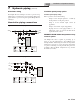
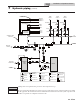
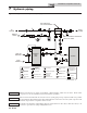
7 Hydronic piping (continued)
DIR #2000585758 00
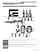
LEGEND
AIR SEPARATOR
CIRCULATION
PUMP
FLOW CHECK VALVE
PRESSURE GAUGE
P
TEMPERATURE &
PRESSURE GAUGE
TP
SYSTEM SUPPLY
SENSOR
BACKFLOW
PREVENTER
MAGNETIC SEPARATOR
WATER METER
STRAINER / FILTER
PRESSURE
REDUCING VALVE
PRESSURE RELIEF
VALVE
BALL VALVE
EXPA NSIO N TANK
PIPING
DRAIN PORT
DIFFERENTIAL
PRESSURE
BYPASS VALVE
2 WAY MOTORIZED
VALVE (OPTIONAL)
MIXING VALVE
ANTI SCALD
FLOW SWITCH
WIRING
INDIRECT
DHW
TANK
BOILER
COLD
WATER IN
TP
MAKE UP
WATER
P
TO
SYSTEM
MULTI TEMP.
LOOP CNTL
(OPTIONAL)
FROM
SYSTEM
TEMP
LOOP 3
TEMP
LOOP 2
TEMP
LOOP 1
24VAC SIGNAL TO
MIXING VALVES
SHEILDED CABLE
TO BOILER
120VAC
TO PUMPS
WIRES TO
LOOP SENSORS
SENSOR 1
PUMP 1
VALVE 1
SENSOR 3
SENSOR 2
PUMP 3
PUMP 2
VALVE 3
VALVE 2
SENSOR 1 SENSOR 2 SENSOR 3
PUMP 1 PUMP 2
PUMP 3
VALVE 1 VALVE 2 VALVE 3
DWH HOT
WATER OUT
Figure 7-8 Single Boiler - Multiple Temperatures with DHW Piped as a Zone
Please note that these illustrations are meant to show system piping concept only, the installer is responsible
for all equipment. e installer must follow all manufacturer’s instructions for each system component. e
installer is responsible for compliance with local codes.
NOTICE
Please note that the installer is responsible for ensuring DHW prioritization when piped as a zone.
NOTICE
CAUTION
Mixing valves are required for the protection of low temperature loops.
CAUTION
Indirect water heaters are capable of transferring a limited number of Btu’s into the water. Ensure boiler
output does not not exceed indirect water heater transfer capabilities.
Installation & Operation Manual