
Install Instructions


44
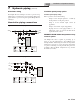
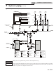
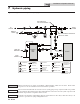
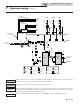
7 Hydronic piping
INDIRECT
DHW
TANK
BOILER
TP
MAKE UP
WATER
P
TO
SYSTEM
FROM
SYSTEM
MAY SUBTITUTE
LOW LOSS HEADER
NOT TO EXCEED 4 PIPE DIA OR
MAX OF 12” APART
LEGEND
AIR SEPARATOR
CIRCULATION
PUMP
FLOW CHECK VALVE
PRESSURE GAUGE
P
TEMPERATURE &
PRESSURE GAUGE
TP
SYSTEM SUPPLY
SENSOR
BACKFLOW
PREVENTER
MAGNETIC SEPARATOR
WATER METER
STRAINER / FILTER
PRESSURE
REDUCING VALVE
PRESSURE RELIEF
VALVE
BALL VALVE
EXPANSION TANK
PIPING
DRAIN PORT
DIFFERENTIAL
PRESSURE
BYPASS VALVE
2 WAY MOTORIZED
VALVE (OPTIONAL)
MIXING VALVE
ANTI SCALD
FLOW SWITCH
WIRING
COLD
WATER IN
DHW HOT
WATER OUT
DIR #2000585755 00
Figure 7-5 Single Boiler - Primary/Secondary Piping
NOTICE
System ow should always remain higher than the required ow for the boiler(s) when the boiler(s) is in
operation to prevent short cycling and high limit issues.
Please note that these illustrations are meant to show system piping concept only, the installer is responsible
for all equipment. e installer must follow all manufacturer’s instructions for each system component. e
installer is responsible for compliance with local codes.
NOTICE
CAUTION
Indirect water heaters are capable of transferring a limited number of Btu’s into the water. Ensure boiler
output does not not exceed indirect water heater transfer capabilities.
Installation & Operation Manual