
Install Instructions


7 Hydronic piping
Near boiler piping components
1. Boiler system piping:
Boiler system piping MUST be sized per the pipe
requirements listed in Table 6B. Reducing the pipe size
can restrict the ow rate through the boiler, causing
inadvertent high limit shutdowns and poor system
performance. Flow rates are based on 20 feet (6 m) of
piping, 4 - 90° elbows, and 2 - fully ported ball valves.
2. Boiler system circulating pump:
Field supplied. e boiler circulating pump should be
based on the heat exchanger pressure drop and any
additional piping.
3. Domestic hot water circulating pump:
Field supplied. e pump MUST be sized to meet
the speci ed minimum ow requirements listed in FIG.
7-3. Consult the indirect water heater operating guide to
determine ow characteristics for the selected product
used.
4. Variable speed boiler system circulator:
Knight XL boilers are capable of controlling a variable
speed boiler system circulator. Variable speed circulators
MUST be sized to meet the speci ed minimum ow
requirements listed in FIG. 7-3 at full speed.
5. Boiler isolation valves:
Field supplied. Full port ball valves are required. Failure
to use full port ball valves could result in a restricted ow
rate through the boiler.
6. Check valves:
Field supplied. Check valves are recommended for
installation as shown in FIG.’s 6-7 through 6-11. Failure
to install check valves could result in a reverse ow
condition during pump(s) o cycle.
7. Domestic indirect hot water isolation valves:
Field supplied. Full port ball valves are required. Failure
to use full port ball valves could result in a restricted ow
rate through the boiler.
8. Anti-scald mixing valve:
Field supplied. An anti-scald mixing valve is
recommended when storing domestic hot water above
115°F (46°C).
9. Unions:
Field supplied. Recommended for unit serviceability.
10. Temperature and pressure gauge:
Factory supplied. e temperature and pressure gauge is
shipped loose. It is the responsibility of the contractor to
install the temperature and pressure gauge on the boiler
water outlet.
11. Pressure relief valve:
Factory supplied. e pressure relief valve is sized to
ASME speci cations.
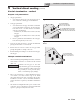
12. Boiler purge valve:
Field supplied. e boiler purge valve is used to
remove entrapped air from the heat exchanger during
start-up.
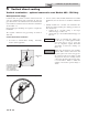
13. System temperature sensor:
Lochinvar supplies a system temperature sensor. e
sensor is to be installed in the heating loop downstream
from the boiler hot water piping and heating loop
junction. e sensor should be located far enough
downstream to sense system diluted water temperature.
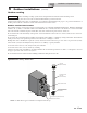
14. Water Meter:
Field supplied. A water meter to monitor makeup water is
recommended. Makeup water volume should not exceed
5% of total system per year.
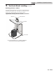
15. Strainer/Filter:
Field supplied. Install a Y-strainer or equivalent multi-
purpose strainer/ lter just before the boiler pump at
the inlet of the heat exchanger. is item is used to
remove system debris from older hydronic systems and
to protect newer systems.
16. Magnetic Separator:
Field supplied. Install a magnetic separator in the
heating system return line as close as practical to the
boiler per the manufacturer’s instructions.
40
Installation & Operation Manual