
Install Instructions


18
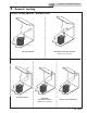
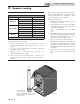
3 General venting
Air inlet pipe materials:
e air inlet pipe(s) must be sealed. Choose acceptable
combustion air inlet pipe materials from the following list:
PVC, CPVC, Polypropylene or ABS
Dryer Vent or Sealed Flexible Duct (not recommended for
roo op air inlet)
Galvanized steel vent pipe with joints and seams sealed as
speci ed in this section.
Type “B” double-wall vent with joints and seams sealed as
speci ed in this section.
AL29-4C, stainless steel material to be sealed to
speci cation of its manufacturer.
*Plastic pipe may require an adapter (not provided) to transition
between the air inlet connection on the appliance and the plastic
air inlet pipe.
Installation & Operation Manual
⚠ WARNING
Using air intake materials other than those
speci ed can result in personal injury, death
or property damage.
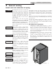
NOTICE
e use of double-wall vent or insulated
material for the combustion air inlet pipe is
recommended in cold climates to prevent
the condensation of airborne moisture in the
incoming combustion air.
Sealing of Type “B” double-wall vent material or galvanized
vent pipe material used for air inlet piping on a sidewall or
vertical roo op Combustion Air Supply System:
a. Seal all joints and seams of the air inlet pipe using either
Aluminum Foil Duct Tape meeting UL Standard 723 or
181A-P or a high quality UL Listed silicone sealant such as
those manufactured by Dow Corning or General Electric.
b. Do not install seams of vent pipe on the bottom of
horizontal runs.
c. Secure all joints with a minimum of three (3) sheet metal
screws or pop rivets. Apply Aluminum Foil Duct Tape or
silicone sealant to all screws or rivets installed in the vent
pipe.
d. Ensure that the air inlet pipes are properly supported.
⚠ DANGER
Failure to properly seal all joints and seams
as required in the air inlet piping may result
in ue gas recirculation, spillage of ue
products and carbon monoxide emissions
causin
g
severe
p
ersonal in
j
ur
y
or death.
e PVC, CPVC, or ABS air inlet pipe should be cleaned and
sealed with the pipe manufacturer’s recommended solvents
and standard commercial pipe cement for the material used.
e PVC, CPVC, ABS, Dryer Vent or Flex Duct air inlet pipe
should use a silicone sealant to ensure a proper seal at the
appliance connection and the air inlet cap connection. Dryer
vent or ex duct should use a screw type clamp to seal the vent
to the appliance air inlet and the air inlet cap. Proper sealing
of the air inlet pipe ensures that combustion air will be free of
contaminants and supplied in proper volume.
Follow the polypropylene manufacturer’s instructions when
using polypropylene material as an inlet pipe.
When a sidewall or vertical roo op combustion air supply
system is disconnected for any reason, the air inlet pipe
must be resealed to ensure that combustion air will be free of
contaminants and supplied in proper volume.
Common venting
Knight XL boilers may be common vented; however, the
following criteria MUST BE followed:
1. Only Knight XL boilers may be connected to the common
vent. DO NOT mix other manufacturer’s appliances or
other Lochinvar models.
2. Knight XL boilers connected to the common vent must all be
of the same size.
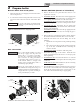
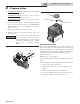
3. Each Knight XL boiler must have a Lochinvar supplied ue
damper installed (see Table 3E).
4. A condensate drain must be installed above the ue damper.
5. Only vertical direct vent, positive pressure, Category IV or
vertical/chimney vent, negative pressure, Category II may
be used when common venting Knight XL boilers. Sidewall
common venting is not allowed.
6. Knight XL boilers in a common vent must be connected
and controlled with the integral Knight XL SMART TOUCH
Cascade.
a. e leader may be controlled through the Knight XL
SMART TOUCH control through BMS (external
0-10V signal), ModBus, BACnet, or its own internally
calculated set point.
b. e Cascade (Members) must be controlled by the
Knight XL Leader water heater using the Lead/Lag
Cascade option.
For approved common vent sizing, contact the factory.
Knight XL boilers cannot be connected using a common air
system.
⚠ WARNING
When Knight XL boilers are common vented,
the criteria above MUST BE followed. Failure
to follow all these requirements will result in
severe personal injury, death, or substantial
property damage.
NOTICE
A eld supplied inline condensate collection
section MUST BE installed directly above the
back ow preventer.
⚠ WARNING
When Knight XL boilers are common vented,
hot water generators must be piped to the
primary heating loop and tank thermostats
must not be connected to the Knight XL.
Flue Damper Kits
Model Damper Size Kit Number
400 4" 100056141
500 4" 100056141
650 4" 100056141
800 6" 100056142
1000 6" 100056142
Table 3E Flue damper kits