
Install Instructions
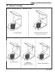


2 Prepare boiler
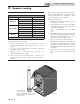
14
DIR #2000582949 00
DIR #2000582949 0
0
DIR
#
2
0
0
0
5
8
2
9
4
9
0
0
DIR #2000582949 0
0
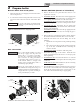
ALLEN
WRENCH
ADJUSTMENT
SCREW
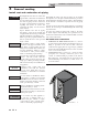
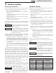
Figure 2-3 Gas Valve Adjustment - Models 400-500
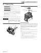
10. For Models 400-500: Remove the front panel from the unit
(no tools required for removal).
For Models 650-1000: Remove the top access cover from
the unit (no tools required for removal).
11. For Models 650-1000: Remove the cover on top of the gas
valve (FIG. 2-4).
12. Use a combustion analyzer to verify CO
2
is within the range
of 9.4 – 10.4%. If not, adjust the screw counterclockwise
incrementally to raise CO
2
and clockwise to lower CO
2
(FIG. 2-3 and 2-4).
13. Replace the gas valve cover and access covers.
14. Replace the front access panel removed in Step 1 and
resume operation.
COVER
A
LLEN WRENCH
ADJUSTMENT SCREW
Figure 2-4 Gas Valve Adjustment - Models 650 - 1000
⚠ WARNING
A er converting to LP, check combustion
per the Start-up procedure in Section 11
of this manual. Failure to check and verify
combustion could result in severe personal
injury, death, or substantial property
damage.
Installation & Operation Manual
Combustion air fi lter
is unit has a standard air lter located at the combustion air
inlet. is air lter is provided to help ensure clean air is used
for the combustion process. Check this lter every month and
replace when it becomes dirty. You can nd these commercially
available lters at any home center or HVAC supply store.
Filters by model sizes:
KBX0400-1000 / 12 x 12 x 1 lter
Note: Replacement lter should have a MERV rating no greater
than 4.
Follow the steps below when replacing the combustion air lter:
1. Locate the combustion air lter box.
2. Li and remove the air lter box cover to gain access to the
air lter.
3. Slide the air lter out the top of the air lter box.
4. Inspect the air lter for dirt and debris, replace if necessary.
5. Replace the air lter and the air lter box cover.