00329949_2000586636_Rev E Installation & Operation Manual Models: 400 - 1000 Series 100 & 101 ⚠ WARNING This manual must only be used by a qualified heating installer / service technician. Read all instructions, including this manual and the Knight XL Service Manual, before installing. Perform steps in the order given. Failure to comply could result in severe personal injury, death, or substantial property damage. Save this manual for future reference.
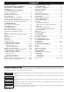
Contents HAZARD DEFINITIONS .................................................. 2 PLEASE READ BEFORE PROCEEDING ..................... 3 THE KNIGHT XL -- HOW IT WORKS ......................... 4-6 RATINGS .......................................................................... 7 1. DETERMINE BOILER LOCATION Provide Air Openings to Room ........................................ 10 Flooring and Foundation ................................................. 10 Residential Garage Installation .....................
Installation & Operation Manual Please read before proceeding ⚠ WARNING NOTICE Installer – Read all instructions, including this manual and the Knight XL Service Manual, before installing. Perform steps in the order given. User – This manual is for use only by a qualified heating installer/service technician. Refer to the User’s Information Manual for your reference. Have this boiler serviced/inspected by a qualified service technician, at least annually.
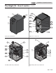
Installation & Operation Manual The Knight XL - How it works... 1. 2. Stainless steel heat exchanger 19. Boiler drain port Allows system water to flow through specially designed coils for maximum heat transfer, while providing protection against flue gas corrosion. The coils are encased in a jacket that contains the combustion process. 20. Low voltage connection board Combustion chamber access cover 21.
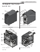
Installation & Operation Manual The Knight XL - How it works...
Installation & Operation Manual The Knight XL - How it works...
Installation & Operation Manual Ratings Knight XL Boiler AHRI Rating Input MBH Model Number Note: Change “N” to “L” for L.P. gas models. (Note 2) Other Specifications Gross Output MBH Net AHRI Ratings Water, MBH Boiler Water Content Gallons Vent Size Water Gas Air Connections Connections Size Min Max (Note 1) (Note 2) KBX0400(N,L) 39.9 399 387 337 4.4 2" 1" 4" 4" KBX0500(N,L) 50 500 485 422 4.9 2" 1" 4" 4" KBX0650(N,L) 65 650 631 549 6.
Installation & Operation Manual 1 Determine boiler location Installation must comply with: • Local, state, provincial, and national codes, laws, regulations, and ordinances. • National Fuel Gas Code, ANSI Z223.1 – latest edition. • Standard for Controls and Safety Devices for Automatically Fired Boilers, ANSI/ASME CSD-1, when required. • National Electrical Code. • For Canada only: B149.1 Installation Code, CSA C22.1 Canadian Electrical Code Part 1 and any local codes.
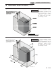
Installation & Operation Manual 1 Determine boiler location (continued) Figure 1-1 Closet Installation - Minimum Required Clearances ⚠ WARNING For closet installations, CPVC, polypropylene or stainless steel vent material MUST BE used in a closet structure due to elevated temperatures. Failure to follow this warning could result in fire, personal injury, or death.
Installation & Operation Manual 1 Determine boiler location Provide air openings to room: Residential garage installation Knight XL alone in boiler room Precautions 1. No air ventilation openings into the boiler room are needed when clearances around the Knight XL are at least equal to the SERVICE clearances shown in FIG.’s 1-1 and 1-2. For spaces that do NOT supply this clearance, provide two openings as shown in FIG. 1-1.
Installation & Operation Manual 1 Determine boiler location Table 1A Corrosive Contaminants and Sources Products to avoid: Spray cans containing chloro/fluorocarbons Permanent wave solutions Chlorinated waxes/cleaners (continued) When using an existing vent system to install a new boiler: Failure to follow all instructions can result ⚠ WARNING in flue gas spillage and carbon monoxide emissions, causing severe personal injury or death.
Installation & Operation Manual 1 Determine boiler location When removing a boiler from existing common vent system: ⚠ DANGER Do not install the Knight XL into a common vent with any other appliance. This will cause flue gas spillage or appliance malfunction, resulting in possible severe personal injury, death, or substantial property damage.
Installation & Operation Manual 2 Prepare boiler Remove boiler from wood pallet Models 400-1000 (Venturi w/ LP Orifices) 1. After removing the outer shipping carton from the boiler, remove the parts box. 1. Remove the front access panel from the unit (no tools required for removal). 2. To remove the boiler from the pallet remove the four (4) lag bolts located at the front and rear of the boiler (FIG. 2-1). 2.
Installation & Operation Manual 2 Prepare boiler 10. For Models 400-500: Remove the front panel from the unit (no tools required for removal). Figure 2-4 Gas Valve Adjustment - Models 650 - 1000 COVER For Models 650-1000: Remove the top access cover from the unit (no tools required for removal). 11. For Models 650-1000: Remove the cover on top of the gas valve (FIG. 2-4). ALLEN WRENCH 12. Use a combustion analyzer to verify CO2 is within the range of 9.4 – 10.4%.
Installation & Operation Manual 3 General venting Direct venting options - Sidewall Vent DIR #2000583014 00 DIR #2000583013 00 Two Pipe Sidewall PVC/CPVC Concentric Sidewall Models 400 - 500 Only Direct venting options - Vertical Vent DIR #2000583016 00 DIR #2000583017 00 DIR #2000583015 00 Two Pipe Vertical PVC/CPVC Concentric Vertical Models 400 - 500 Only Vertical Vent, Sidewall Air 15
Installation & Operation Manual 3 General venting Install vent and combustion air piping ⚠ DANGER The Knight XL boiler must be vented and supplied with combustion and ventilation air as described in this section. Ensure the vent and air piping and the combustion air supply comply with these instructions regarding vent system, air system, and combustion air quality. See also Section 1 of this manual.
Installation & Operation Manual 3 General venting (continued) Requirements for installation in Canada 1. 2. 3. 4. Installations must be made with a vent pipe system certified to ULC-S636. The first three (3) feet of plastic vent pipe from the appliance flue outlet must be readily accessible for visual inspection. The components of the certified vent system must not be interchanged with other vent systems or unlisted pipe/fittings.
Installation & Operation Manual 3 General venting Air inlet pipe materials: Common venting The air inlet pipe(s) must be sealed. Choose acceptable combustion air inlet pipe materials from the following list: Knight XL boilers may be common vented; however, the following criteria MUST BE followed: PVC, CPVC, Polypropylene or ABS Dryer Vent or Sealed Flexible Duct (not recommended for rooftop air inlet) Galvanized steel vent pipe with joints and seams sealed as specified in this section.
Installation & Operation Manual 3 General venting Common venting CAT II: (continued) Table 3G Optional Room Air Kit Flues of multiple appliances may be combined by incorporating a vent increaser to change the Category IV appliance to a Category II vent system which can be common vented using an engineered vent system. An increaser must be used and the combined engineered vent system must be designed to ensure that flue products will be properly exhausted from the building at all times.
Installation & Operation Manual 3 General venting Table 3H PVC/CPVC Vent Pipe and Fittings 5. Dry fit vent or air piping to ensure proper fit up before assembling any joint. The pipe should go a third to two-thirds into the fitting to ensure proper sealing after cement is applied. 6.
Installation & Operation Manual 3 General venting (continued) Polypropylene NOTICE This product has been approved for use with polypropylene vent with the manufacturers listed in Table 3H. All terminations must comply with listed options in this manual and be a single-wall vent offering. Installation of a polypropylene vent system should adhere to the vent manufacturer’s installation instructions supplied with the vent system.
Installation & Operation Manual 3 General venting Stainless steel vent Figure 3-5 Near Boiler Stainless Steel Venting Models 400 - 1000 This product has been approved for use with stainless steel using the manufacturers listed in Table 3K. Use only the materials, vent systems, and ⚠ WARNING terminations listed in Tables 3I and 3K. DO NOT mix vent systems of different types or manufacturers. Failure to comply could result in severe personal injury, death, or substantial property damage.
Installation & Operation Manual 4 Sidewall direct venting Vent/air termination – sidewall ⚠ WARNING Follow instructions below when determining vent location to avoid possibility of severe personal injury, death, or substantial property damage. A gas vent extending through an exterior ⚠ WARNING wall shall not terminate adjacent to a wall or below building extensions such as eaves, parapets, balconies, or decks.
Installation & Operation Manual 4 Sidewall direct venting Vent/air termination – sidewall c. Figure 4-2A Alternate PVC/CPVC/ Polypropylene Sidewall Termination w/Field Supplied Fittings BIRD SCREEN TO BOILER INTAKE AIR CONNECTION 12" (305 MM) MIN Do not terminate closer than 4 feet (1.2 m) horizontally from any electric meter, gas meter, regulator, relief valve, or other equipment. Never terminate above or below any of these within 4 feet (1.2 m) horizontally. 6.
Installation & Operation Manual 4 Sidewall direct venting (continued) Vent/air termination – sidewall Figure 4-4A Clearance to Forced Air Inlets 2. IF LESS THAN 10’ VENT / AIR TERMINATION 36" MIN. FORCED AIR INLET 3. 3. 5. 6. 7' MIN. ABOVE ANY PUBLIC WALKWAY Figure 4-4B Alternate Clearance to Forced Air Inlets w/Field Supplied Fittings 7. 8. IF LESS THAN 10’ (3 M) 9. For Polypropylene Only: Install the vent and air intake sidewall adapters from Table 3H into the vent plate.
Installation & Operation Manual 4 Sidewall direct venting Figure 4-5B Polypropylene Sidewall Termination Assembly Multiple vent/air terminations SIDEWALL ADAPTER (AIR) WALL PLATE SIDEWALL RETAINING PLATE 1. When terminating multiple Knight XL’s terminate each vent/air connection as described in this manual (FIG. 4-6A). ⚠ WARNING VENT PLATE VENT CAP SIDEWALL ADAPTER (VENT) GALVANIZED THIMBLE IMG00085 Prepare wall penetrations (Alternate - Field Supplied Option) 1. 2. 3. 4. 5.
Installation & Operation Manual 4 Sidewall direct venting (continued) Sidewall termination – optional concentric vent: Models 400 - 500 Only Description and usage Lochinvar offers an optional concentric combustion air and vent pipe termination kit (#100140484 for 4" (102 mm) diameter - Models 400 - 500). Both combustion air and vent pipes must attach to the termination kit. The termination kit must terminate outside the structure and must be installed as shown below in FIG. 4-7.
Installation & Operation Manual 4 Sidewall direct venting Sidewall termination – optional concentric vent: Models 400 - 500 Only Figure 4-9 Concentric Vent Dimensional Drawing - Models 400 - 500 "A" "C" DIA. "B" DIA. "D" 3" (76 MM) "E" "G" "H" DIA. "B" DIA.
Installation & Operation Manual 4 Sidewall direct venting (continued) Sidewall termination – optional concentric vent: Models 400 - 500 Only Figure 4-11 Concentric Vent Sidewall Attachment STRAP (FIELD SUPPLIED) ELBOW (FIELD SUPPLIED) COMBUSTION AIR COMBUSTION AIR VENT VENT CAUTION DO NOT use field-supplied couplings to extend pipes. Airflow restriction will occur and may cause intermittent operation. 8. Cement appliance combustion air and vent pipes to the concentric vent termination assembly.
Installation & Operation Manual 5 Vertical direct venting Vent/air termination – vertical ⚠ WARNING Follow instructions below when determining vent location to avoid possibility of severe personal injury, death or substantial property damage. Figure 5-1A PVC/CPVC/Polypropylene Termination of Air and Vent Vertical ALTERNATE INTAKE LOCATIONS: INTAKE PIPES MAY BE LOCATED ANYWHERE WITHIN 24" (610 MM) OF VENT PIPE Determine location Locate the vent/air terminations using the following guidelines: 1.
Installation & Operation Manual 5 Vertical direct venting (continued) Vent/air termination – vertical Prepare roof penetrations 1. 2. Air pipe penetration: a. Cut a hole for the air pipe. Size the air pipe hole as close as desired to the air pipe outside diameter. Figure 5-2 Vertical Terminations with Multiple Boilers 12" (305 MM) MINIMUM VERTICALLY FROM VENT OUTLET TO ANY AIR INLET Vent pipe penetration: a. b. Cut a hole for the vent pipe.
Installation & Operation Manual 5 Vertical direct venting Vertical termination – optional concentric vent: Models 400 - 500 Only Description and usage Lochinvar offers an optional concentric combustion air and vent pipe termination kit. Both combustion air and vent pipes must attach to the termination kit. The termination kit must terminate outside the structure and must be installed as shown in FIG. 5-4. Field supplied pipe and fittings are required to complete the installation.
Installation & Operation Manual 5 Vertical direct venting (continued) Vertical termination – optional concentric vent: Models 400 - 500 Only Do not operate the appliance with the rain cap removed or recirculation of combustion products may occur. Water may also collect inside the larger combustion air pipe and flow to the burner enclosure. Failure to follow this warning could result in product damage or improper operation, personal injury, or death. ⚠ WARNING CAUTION 6.
Installation & Operation Manual 5 Vertical direct venting Alternate vertical concentric venting This appliance may be installed with a concentric vent arrangement where the vent pipe is routed through an existing unused venting system; or by using the existing unused venting system as a chase for vent and combustion air routing. Figure 5-8 Concentric Vent Example 1 FLUE EXHAUST SEAL Concentric Venting Arrangement The venting is to be vertical through the roof. The annular space between the O.D.
Installation & Operation Manual 5 Vertical direct venting (continued) Existing vent as a chase Follow all existing termination and clearance requirements and allowable pipe lengths. Use only approved venting materials listed in the General Venting Section of this manual. Figure 5-10 Existing Vent as a Chase AIR INLET FLUE EXHAUST SEAL EXISTING CAP SEAL FLUE OUTLET DIR #2000585169 00 *For concept illustration only. Individual installations may vary due to job site specific equipment.
Installation & Operation Manual 6 Outdoor installations Outdoor venting Outdoor vent / air inlet location • Keep venting areas free of obstructions. Keep area clean and free of combustible and flammable materials. Maintain minimum clearances to combustibles as stated in this manual. • • • • • • In order to properly install the appliance in an outdoor configuration, the appropriate outdoor ready model (ex. KBX0400N-O) must be purchased WITH a factory supplied outdoor installation kit.
Installation & Operation Manual 6 Outdoor installations (continued) Outdoor venting NOTICE Before installing a venting system, follow all requirements found in the General Venting section. Units are self-venting and can be used outdoors when installed with the optional outdoor kit. Combustion air supply must be free of contaminants (see Combustion and Ventilation Air, page 10). To prevent recirculation of the flue products into the combustion air inlet, follow all instructions in this section.
Installation & Operation Manual 7 Hydronic piping System water piping methods The Knight XL is designed to function in a closed loop pressurized system not less than 12 psi (83 kPa) (Nonmetallic system piping must have an oxygen barrier to be considered a closed loop). A temperature and pressure gauge is included to monitor system pressure and outlet temperature and should be located on the boiler outlet.
Installation & Operation Manual 7 Hydronic piping NOTICE (continued) A magnetic separator is recommended when a unit is installed in a retrofit system or a system containing steel and/or cast iron pipe. See the piping illustrations included in this section, FIG.’s 7-4 thru 7-8 for suggested guidelines in piping the Knight XL. NOTICE Please note that these illustrations are meant to show system piping concept only, the installer is responsible for all equipment and detailing required by local codes.
Installation & Operation Manual 7 Hydronic piping Near boiler piping components 1. Boiler system piping: Boiler system piping MUST be sized per the pipe requirements listed in Table 6B. Reducing the pipe size can restrict the flow rate through the boiler, causing inadvertent high limit shutdowns and poor system performance. Flow rates are based on 20 feet (6 m) of piping, 4 - 90° elbows, and 2 - fully ported ball valves. 2. Boiler system circulating pump: Field supplied.
Installation & Operation Manual 7 Hydronic piping (continued) Circulator sizing Variable speed pump option The Knight XL heat exchanger does have a pressure drop, which must be considered in your system design. Refer to the graphs in FIG 7-3 pressure drop through the Knight XL heat exchanger.
Installation & Operation Manual 7 Hydronic piping Figure 7-3 Pressure Drop vs. Flow PRESSURE DROP VS FLOW (HEAT EXCHANGER ONLY) 400 500 650 800 1000 60 PRESSURE DROP (FT.
Installation & Operation Manual 7 Hydronic piping (continued) Figure 7-4 Single Boiler - Multiple Temperatures WIRES TO LOOP SENSORS TEMP LOOP 1 SENSOR 1 SENSOR 2 SENSOR 3 120VAC TO PUMPS TEMP LOOP 3 SENSOR 1 SENSOR 2 SENSOR 3 PUMP 1 PUMP 2 PUMP 3 VALVE 1 VALVE 2 VALVE 3 PUMP 1 PUMP 2 PUMP 3 MULTI TEMP.
Installation & Operation Manual 7 Hydronic piping Figure 7-5 Single Boiler - Primary/Secondary Piping MAY SUBTITUTE LOW LOSS HEADER TO SYSTEM FROM SYSTEM P MAKE UP WATER NOT TO EXCEED 4 PIPE DIA OR MAX OF 12” APART INDIRECT DHW TANK DHW HOT WATER OUT BOILER T P COLD WATER IN AIR SEPARATOR BACKFLOW PREVENTER DIFFERENTIAL PRESSURE BYPASS VALVE PRESSURE RELIEF VALVE FLOW SWITCH P DRAIN PORT MAGNETIC SEPARATOR T P TEMPERATURE & PRESSURE GAUGE PRESSURE GAUGE WATER METER 2 WAY MOTORIZED VA
Installation & Operation Manual 7 Hydronic piping (continued) Figure 7-6 Multiple Boilers - Multiple Temperatures Number of Units Model 400 500 650 800 1000 2 3 4 5 6 7 8 Required Pipe Sizes in NPT (Based on 30°△) 2.5 3 3 4 4 3 4 4 4 6 WIRES TO LOOP SENSORS TEMP LOOP 1 SENSOR 1 SENSOR 2 SENSOR 3 120VAC TO PUMPS 4 4 4 6 6 4 4 6 6 6 TEMP LOOP 2 6 6 6 6 8 6 6 6 8 8 TEMP LOOP 3 SENSOR 1 SENSOR 2 SENSOR 3 PUMP 1 PUMP 2 PUMP 3 VALVE 1 VALVE 2 VALVE 3 PUMP 1 PUMP 2 PUMP 3 MULTI TEMP.
Installation & Operation Manual 7 Hydronic piping Figure 7-7 Multiple Boilers - Primary/Secondary Piping Number of Units 2 3 4 5 6 7 8 Required Pipe Sizes in NPT (Based on 30°△) Model 400 500 650 800 1000 2.
Installation & Operation Manual 7 Hydronic piping (continued) Figure 7-8 Single Boiler - Multiple Temperatures with DHW Piped as a Zone WIRES TO LOOP SENSORS TEMP LOOP 1 SENSOR 1 SENSOR 2 SENSOR 3 120VAC TO PUMPS TEMP LOOP 3 SENSOR 1 SENSOR 2 SENSOR 3 PUMP 1 PUMP 2 PUMP 3 VALVE 1 VALVE 2 VALVE 3 PUMP 1 PUMP 2 PUMP 3 MULTI TEMP.
Installation & Operation Manual 8 Gas connections Connecting gas supply piping 1. Remove the top access panel and refer to FIG.’s 8-1 thru 8-2 to pipe gas to the boiler. a. Install ground joint union for servicing, when required. b. Install a manual shutoff valve in the gas supply piping outside boiler jacket when required by local codes or utility requirements. c. In Canada – When using manual main shutoff valves, it must be identified by the installer. 2. Install sediment trap / drip leg.
Installation & Operation Manual 8 Gas connections ⚠ WARNING (continued) Failure to apply pipe sealing compound as detailed in this manual can result in severe personal injury, death, or substantial property damage. Use two wrenches when tightening gas ⚠ WARNING piping at boiler (FIG. 8-3), using one wrench to prevent the boiler gas line connection from turning. Failure to support the boiler gas connection pipe to prevent it from turning could damage gas line components.
Installation & Operation Manual 8 Gas connections Table 8A Natural Gas Pipe Size Chart Capacity of Schedule 40 Metallic Pipe in Cubic Feet of Natural Gas Per Hour (based on .60 specific gravity, 0.30" w.c.
Installation & Operation Manual 8 Gas connections (continued) When re-tightening the set screw, be sure ⚠ WARNING to tighten securely to prevent gas leaks. Figure 8-5 Inlet Gas Supply Check - Models 650 - 1000 Do not check for gas leaks with an open flame -- use the bubble test. Failure to use the bubble test or check for gas leaks can cause severe personal injury, death, or substantial property damage. DETAIL 14. Turn on the gas supply at the manual gas valve. 15.
Installation & Operation Manual 9 Field wiring ⚠ WARNING NOTICE ⚠ CAUTION ELECTRICAL SHOCK HAZARD – For your safety, turn off electrical power supply before making any electrical connections to avoid possible electric shock hazard. Failure to do so can cause severe personal injury or death. Installation must comply with: 1. National Electrical Code and any other national, state, provincial, or local codes, or regulations. 2. In Canada, CSA C22.1 Canadian Electrical Code Part 1, and any local codes.
Installation & Operation Manual 9 Field wiring (continued) Thermostat 1. Connect the room thermostats or end switches (isolated contact only) to heat/loop demand 1, 2, or 3, as shown in FIG. 9-3. 2. Install the thermostat on the inside wall away from influences of drafts, hot or cold water pipes, lighting fixtures, television, sunlight, or fireplaces. 3. Thermostat anticipator (if applicable): a. If connected directly to boiler, set for 0.1 amps. b.
Installation & Operation Manual 9 Field wiring Modbus / BACnet Alarm contacts When the optional ModBus / BACnet interface module is installed, the RS-485 ModBus / BACnet cable is connected to these terminals. Use shielded, 2-wire twisted pair cable. If desired, the shield can be connected to ground by installing a jumper wire between terminals 1 and 3 on connector X5 on the optional ModBus / BACnet interface module.
COM NO ROOM THERMOSTAT 1 ROOM THERMOSTAT 2 ROOM THERMOSTAT 3 TANK THERMOSTAT FLOW SWITCH WIRE AS NEEDED BOILER PUMP SYSTEM PUMP SPEED CONTROL BUILDING MANAGEMENT SYSTEM AB SHIELD IMG00127 NOTE: CONNECTION BOARD SPLIT FOR ILLUSTRATION PURPOSES SYSTEM SUPPLY SENSOR OUTDOOR SENSOR TANK SENSOR Field wiring LOUVER PROVING SWITCH LOUVER RELAY SHIELD A TO B NEXT BOILER 9 LOW WATER CUTOFF FROM A PREVIOUS B BOILER Installation & Operation Manual (continued) Figure 9-3 Low Voltage Field Wir
Installation & Operation Manual 10 Condensate disposal Condensate drain 1. This boiler is a high efficiency appliance that produces condensate. NOTICE Use materials approved by the authority having jurisdiction. In the absence of other authority, PVC and CPVC pipe must comply with ASTM D1785 or D2845. Cement and primer must comply with ASME D2564 or F493. For Canada use CSA or ULC certified PVC or CPVC pipe, fittings, and cement.
Installation & Operation Manual 11 Start-up Pre-Commissioning Cleaning 1. Prior to fill and start-up, flush the entire heating system. 2. Clean the entire heating system with an approved precommissioning cleaner (comparable to Sentinel X300 or Fernox F3) in accordance with the manufacturer’s recommendation to remove debris and prolong the life of the heat exchanger. Boiler water CAUTION DO NOT use "homemade cures" or "boiler patent medicines".
Installation & Operation Manual 11 Start-up 1. Use glycol only if needed for freeze protection fluid. Fill and test water system 2. Propylene glycol is the recommended freeze protection fluid. 1. Fill system only after ensuring the water meets the requirements of this manual. 3. Make sure to flush the boiler system before adding glycol. 4. Determine the freeze protection fluid quantity using system water content, following the fluid manufacturer's instructions.
Installation & Operation Manual 11 Start-up (continued) Check for gas leaks ⚠ WARNING Before starting the boiler, and during initial operation, smell near the floor and around the boiler for gas odorant or any unusual odor. Remove the top access panel and smell the interior of the boiler enclosure. Do not proceed with startup if there is any indication of a gas leak. Use an approved leak detection solution. Repair any leaks at once. DO NOT adjust gas valve outlet pressure.
Installation & Operation Manual 11 Start-up Condensate drain NOTICE Use materials approved by the authority having jurisdiction. In the absence of other authority, PVC and CPVC pipe must comply with ASTM D1785 or D2845. Cement and primer must comply with ASME D2564 or F493. For Canada use CSA or ULC certified PVC or CPVC pipe, fittings, and cement. NOTICE To allow for proper drainage on large horizontal runs, a second line vent may be required and tubing size may need to increase to 1 inch.
Installation & Operation Manual 11 Start-up (continued) Final checks before starting the boiler Check vent piping and air piping Read the Knight XL Boiler Service Manual to familiarize yourself with SMART TOUCH control module operation. Read the preceding Startup sections in this manual, for proper steps to start the boiler. 1. Check for gastight seal at every connection, seam of air piping, and vent piping.
Installation & Operation Manual 11 Start-up Figure 11-2 Operating Instructions FOR YOUR SAFETY READ BEFORE OPERATING WARNING: If you do not follow these instructions exactly, a fire or explosion may result causing property damage, personal injury, or loss of life. A. This appliance does not have a pilot. It is equipped with an ignition device which automatically lights the burner. Do not try to light the burner by hand. B. BEFORE OPERATING smell all around the appliance area for gas.
Installation & Operation Manual 11 Start-up (continued) Check flame and combustion (continued) Set space heating operation 4. Navigate to the Setup Screen from the Home Screen by pressing the SETUP button along the left side of the screen. Enter the installer password. Determine controlling sensor 5. Select the Service Maintenance Screen. The tabs will scroll (up and down) to reveal more options. See the Knight XL Service Manual for more detailed information. 6.
Installation & Operation Manual 11 Start-up Adjust set point temperature(s) During normal operation, set point temperatures can be adjusted from the Home Screen by pressing the DETAILS button on the bottom of the screen (see FIG. 11-3). 1. To change a set point, use the set point slider feature or the PLUS (+) and MINUS (-) buttons to adjust the set points as shown in FIG. 11-3. 2. Once the set point has been adjusted to the desired setting, press the Door Menu slider (top left) or the Setup button.
Installation & Operation Manual 11 Start-up (continued) Set domestic hot water (DHW) operation Set maximum DHW fan speed Verify DHW mode If the rated input of the indirect tank is less than the maximum output of the boiler, change the maximum DHW fan speed setting to limit the boiler output accordingly, see the Knight XL Service Manual for a detailed explanation of this procedure. There are two (2) modes of operation for DHW.
Installation & Operation Manual 11 Start-up Configuration of the cascade NOTE: For more detailed instructions, please refer to the Knight XL Service Manual. When installing a Cascade system, all units must be programmed for Cascade to operate. Access the Cascade Setup options as follows: 1. Press the SETUP button on the left side of the display screen. 2. Enter the installer password. 3. Select the Cascade option as shown in FIG. 11-5. 4. Each unit must have a unique address set.
Installation & Operation Manual 12 Operating information General DHW priority How the boiler operates The SMART TOUCH control allows the connection of a DHW thermostat or tank sensor to the low voltage connection board. When a tank sensor is connected, the DHW thermostat input is ignored. When a boiler is programmed for DHW Normal Mode, the maximum firing rate can be limited to match the input rating of the indirect tank coil.
Installation & Operation Manual 12 Operating information Temperature control Modulation The Knight XL is capable of modulating its firing rate from a minimum of 10% to a maximum of 100%. The firing rate is dictated by the call for heat (i.e., space heating or domestic hot water), the heating load, ramp delay (if enabled), and various other temperature limitations.
Installation & Operation Manual 12 Operating information (continued) Freeze protection (continued) Error logging Neither this feature, the boiler control module, nor the use of glycol eliminates the possibility of freezing. The installation must still use recognized design, installation, and maintenance practice to prevent freeze potential for the boiler and system. The control will hold in memory the last 10 lockouts as well as the last 10 blockings.
Installation & Operation Manual 12 Operating information Low water cutoff protection Sequence of the cascade 1. To equalize the run time of all boilers on the Cascade, the firing sequence will automatically be changed at set intervals. 2. The SMART TOUCH control module uses temperature sensing of both supply and return areas of the heat exchanger. If the flow rate is too low or the outlet temperature too high, the control module modulates and shuts the boiler down.
Installation & Operation Manual 12 Operating information (continued) Sequence of operation OPERATION 1. Upon a call for heat, the gas pressure switch(es) must be closed. 2. Once the gas pressure switch(es) are closed, the control turns on the appropriate pumps (system and boiler pumps for space heating, DHW pump for DHW). The flow switch and/or LWCO must close. 3. The control turns on power to the louver relay. The louver proving switch, air pressure switch, and blocked drain switch must close. 4.
Installation & Operation Manual 12 Operating information Knight XL control module Use the control panel (FIG. 12-1) to set temperatures, operating conditions, and monitor boiler operation. Figure 12-1 Control Panel HOME VIEW SETUP INFORMATION SETTINGS • The Status Section is located on the top left of the screen and displays how the unit is currently running (i.e.
Installation & Operation Manual 13 Maintenance Maintenance and annual startup Table 13A Service and Maintenance Schedules Service technician (see the following pages for instructions) Owner maintenance (see the Knight XL User’s Information Manual for instructions) General: • Address reported problems • Inspect interior; clean and vacuum if necessary; • Clean condensate trap and fill with fresh water • Check boiler area Daily • Check pressure/temperature gauge • Check for leaks (water, gas, flue,
Installation & Operation Manual 13 Maintenance ⚠ WARNING Follow the Service and maintenance procedures given throughout this manual and in component literature shipped with the boiler. Failure to perform the service and maintenance could result in damage to the boiler or system. Failure to follow the directions in this manual and component literature could result in severe personal injury, death, or substantial property damage.
Installation & Operation Manual 13 Maintenance (continued) Check all piping for leaks ⚠ WARNING Eliminate all system or boiler leaks. Continual fresh makeup water will reduce boiler life. Minerals can build up in sections, reducing heat transfer, overheating heat exchanger, and causing heat exchanger failure. Leaking water may also cause severe property damage. 1. Inspect all water and gas piping and verify to be leak free. 2. Look for signs of leaking lines and correct any problems found. 3.
Installation & Operation Manual 13 Maintenance Inspect ignition and flame sense electrodes Figure 13-2 Burner Assembly - Model 400 - 1000 1. Remove the ignition and flame sense electrodes from the boiler heat exchanger access cover. 2. Remove any deposits accumulated on the ignition/flame sense electrode using sandpaper. If the electrodes cannot be cleaned satisfactorily, replace with new ones. 3. Replace ignition/flame sense electrode, making sure gasket is in good condition and correctly positioned.
Installation & Operation Manual 13 Maintenance (continued) Check flame signal 1. At high fire the flame signal shown on the display should be at least 10 microamps. 2. A lower flame signal may indicate a fouled or damaged flame sense electrode. If cleaning the flame sense electrode does not improve, ground wiring is in good condition, and ground continuity is satisfactory, replace the flame sense electrode. 3.
Installation & Operation Manual 14 Diagrams Figure 14-1 Wiring Diagram BOX DEPICTS OPTIONAL ITEMS BOX DEPICTS DUAL SENSOR SINGLE HOUSING LOW VOLTAGE 120 VAC HIGH VOLTAGE LCD DISPLAY WIFI DONGLE COMMUNICATION CONTROL BOARD J3 J11 BELL JUMPER SILENCING SWITCH ALARM BELL CONNECTION BOARD ALARM CONTACTS RUN-TIME CONTACTS 24 VAC LOUVER RELAY COIL LOUVER PROVING SWITCH GAS PRESSURE SWITCH FLOW SWITCH TANK THERMOSTAT HEAT/LOOP DEMAND HEAT/LOOP DEMAND HEAT/LOOP DEMAND 3 2 1 1 2 3 4 5 6 7 8 9 10 J2
Installation & Operation Manual 14 Diagrams (continued) Figure 14-2 Ladder Diagram JUNCTION BOX 120VAC NEUTRAL TERMINAL STRIP 120V SUPPLY "L" TERMINAL STRIP 120V SUPPLY "N" BLOWER RELAY 1 ON / OFF SWITCH INTEGRATED CONTROL X1-6 LOW VOLTAGE 120 VAC HIGH VOLTAGE SYSTEM PUMP CONTACTS BLOWER 3.15A BLOWER RELAY F1 6.
Revision Notes: Revision A (TLA #3000042117 / CN #500030025) initial release. Revision B (PCP #3000042688 / CN # 500030426) reflects an update from SMART SYSTEM to SMART TOUCH. Revision C (PCP #3000043071 / CN #500030823) reflects an update to the high altitude verbiage. Revision D (PCP #3000045192 / CN #500032877) reflects the addition of air filter size information.