
Smart System User Guide

2 SMART SYSTEM Status screen
5
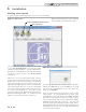
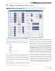
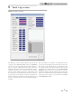
Figure 2-1_SMART SYSTEM Status Screen
To monitor the operation of the heater, click on the Status tab
along the top of the Main Screen window (FIG. 1-1, page 4).
The Status Screen will appear (see FIG. 2-1 above).
The Sensors section displays the current temperatures seen by
the following:
• Inlet
• Outlet 1
• Outlet 2
• System
• Flue 1
• Flue 2 (check / limit)
• Tank
• Outdoor
Relative calculated values such as the Delta T (ΔT) across
the heat exchanger and the voltage being applied to the 0 -
10Vdc BMS input are also shown. The controlling sensor
is shown at the bottom of the Sensors section. The default
controlling sensor is the Outlet sensor. If a System Supply
sensor is connected, the control will automatically use it as the
controlling sensor.
When programmed to control from the Inlet, the Outlet
sensor will be displayed for the first three (3) minutes after
the burner lights, and then the Inlet sensor will be displayed.
Below the temperature readings are the Derivative Flue and
Derivative Outlet fields. These show how quickly these
temperatures are changing. The control will take certain
actions based on these values. For instance, if the outlet
temperature rises too quickly, the control will force the heater
to run at low fire. In the lower right section of the sensor
temperature readings are the various setpoints. The SH1, SH2
and SH3 setpoints are for different space heating demands to
the SMART SYSTEM. The largest of these demands will act as
the system setpoint with system sensor connected. Note that
the use of an outdoor temperature sensor (if used) will drive
the system according to the outdoor air reset parameters.
When the 0 - 10 Vdc input is used, this setpoint will vary with
the input voltage if it is used to control the setpoint. The HW
setpoint is the setpoint used when a Tank sensor is connected.
The dSP setpoint is used to represent the value of the highest
controlling setpoint for space heat that is active. The dSP
can also represent the setpoint when controlling from the
inlet sensor, system, or the outlet temperature setpoint when
heating an indirect tank. At the bottom of the Sensors section
are Night SetB SH and Night SetB HW, which indicates if they
are active or not. Lastly, the Flame current is shown.
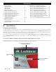
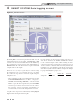
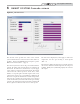
PC Program Instructions