
Smart System User Guide

6 SMART SYSTEM Cascade screen
10
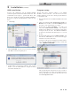
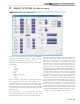
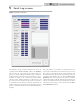
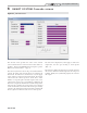
Figure 6-1_Cascade Screen
The Cascade Screen provides the status of the Cascade
system. The PC must be connected to the Leader (address 0)
appliance. Click on the Cascade button along the top of the
Main Screen window (FIG. 1-1, page 4).
The Cascade System area shows the power demand and the
setpoint, the boiler status, and the priority of each heater in
the Cascade. If a tank sensor (water heaters) or system supply
sensor (boilers) is connected to the Leader heater, the Cascade
control will send a fixed setpoint of 185°F (85°C) (boiler
default) or a setpoint equal to the tank setpoint +27°F (15°C)
(water heaters) and a power (% modulation) command to all
the heaters as required to maintain the controlled temperature
at the setpoint. On boilers, if a system sensor is not connected
(NOT recommended), the Leader will send the space heating
setpoint to all of the boilers in the Cascade and each boiler will
fire as required to hold their outlet sensors to this setpoint.
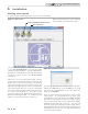
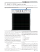
The Sensors area displays the system supply or tank sensor
temperature, and the space heating or tank setpoint
(FIG. 6-1).
The Status area displays the Cascade power actual output for
the Cascade, while Cascade Max represents the total power
available. Finally, the System Pump displays the status for
that output.
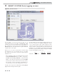
PC Program Instructions