48089 Fremont Blvd Fremont, CA 94538 (510) 623-9600 www.loadstarsensors.com DS-3000U Digital Display Module 4-channel USB Sensor Input Users Guide Copyright © 2008 - 2010 Loadstar Sensors, Inc.. All rights reserved.
DS-3000U DS3000 User Guide Notes: © Copyright 2008 - 2010 Loadstarsensors Inc. All Rights Reserved. No part of this manual may be reproduced in any form or by any means (including electronic storage and retrieval, or translation into a foreign language) without prior agreement and written consent from Loadstar sensors, Inc. as governed by United States and international copyright laws.
DS-3000U DS3000 User Guide WARNING 1. Do not use the display with the cover, or part of the cover, removed or loose as a hazardous condition may result. Inspect the case for cracks or missing plastic. Do not use if the display is damaged. 2. Use only AC Adapter Charger(s), which conforms to the display required voltage and current ratings provided. 3. Do not operate the display in an explosive atmosphere, or in the presence of flammable gases or fumes. 4.
DS-3000U DS3000 User Guide The Directive aims to reduce the waste arising from electrical and electronic equipment, and improve the environmental performance of everything involved in the life cycle of electrical and electronic equipment. This is translated into the following requirements: Producers (manufacturers or importers) of electrical and electronic equipment will be required to register in their countries.
DS-3000U DS3000 User Guide that are sold into the China market have the required marking on the product designating that the product meets the China RoHS requirements. The second step involving a testing obligation is currently under development. Full compliance will follow once it has been finalized. Table of contents: 1 2 3 4 5 6 7 8 9 I WANT TO: ..............................................................................................................................7 INTRODUCTION .............
DS-3000U DS3000 User Guide 9.3 Go/NoGo Acceptable Weight Limit Test .......................................................................... 32 9.3.1 Application Requirements: ........................................................................................ 33 9.3.2 Implementation Details: ............................................................................................. 33 9.3.3 Programming the DS-3000:..................................................................................
DS-3000U DS3000 User Guide 1 I WANT TO: 1. Quickly understand the DS-3000 user interface –or2. Get Started Quickly with the DS-3000 5 OPERATION QUICK START GUIDE ..................................................................................... 14 3. 6 Get to programming mode on the DS-3000? RUNNING OR PROGRAMMING? .......................................................................................... 16 4. See a list of common DS-3000 programming tips 7 QUICK PROGRAMMING HOW-TO TIPS .........
DS-3000U DS3000 User Guide 2 INTRODUCTION The Loadstar Sensors DS-3000 portable display provides a convenient method of monitoring loads on up to four Loadstar load cells simultaneously. The DS-3000 device supports the complete range of Loadstar’s iLoad USB load cell line: the iLoad Digital USB, iLoad Pro Digital USB, iLoad TR Digital load cells, the iLoad Mini when paired with the DQ-1000U Frequency to USB converter, and the complete FlexiSensor line when paired with the CS2000/CS4000.
DS-3000U DS3000 User Guide 3 MODULE FEATURES • Power input may be provided either by the provided AC adapter (90-250 VAC 50/60 Hz) or an optional DC input pigtail (9-32 VDC). • Precise six digit display plus sign (+9.9.9.9.9.9./-9.9.9.9.9.9.) provides properly scaled output (in selectable units and precision) for compatible Loadstar sensor inputs.. • Connected sensor(s) are powered by the display module. No additional power supply is required.
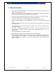
DS-3000U DS3000 User Guide 4 PHYSICAL DETAILS The following pictures of the DS-3000 Display module show the locations of all exterior connections, the user interface, and the optional mounting base. Descriptions of each are in the following sections. 4.
DS-3000U DS3000 User Guide USB HOST POWER INPUT Figure 3: End View: Power and USB Host Connections Loadstar Sensors, Inc. Page: 11 / 48 033-01419 Rev.
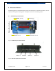
DS-3000U DS3000 User Guide Contact 2 Contact 1 Remote contacts TARE/TRIGGER Figure 4: End View: Wiring Adapter Socket 4.2 DS-3000 Mechanical Dimensions Figure 5: DS-3000 Top View (Includes optional mounting base) Loadstar Sensors, Inc. Page: 12 / 48 033-01419 Rev.
DS-3000U DS3000 User Guide Figure 6: DS-3000U Mechanical Host End View Figure 7: DS-3000U Mechanical Side View Loadstar Sensors, Inc. Page: 13 / 48 033-01419 Rev.
DS-3000U DS3000 User Guide 5 OPERATION QUICK START GUIDE When power is first applied to the DS-3000 Series display, all segments of the LED display will be momentarily illuminated,(-88888888) while the instrument goes through an internal self test procedure.
DS-3000U 5.2 DS3000 User Guide • In programming mode, this button steps DOWN/FUNCTION in the currently selected menu tree, or decrements the current highlighted digit in a numeric entry field. • The DOWN/FUNCTION key will be abbreviated down in the remainder of this document. Getting Started Figure 8: What you need to get started with the DS-3000 If you plan to communicate with the DS-3000U from a PC and/or use LoadVUE software with it, install the PC drivers and/or LoadVUE on the PC first.
DS-3000U DS3000 User Guide 6 RUNNING OR PROGRAMMING? Default DS-3000 operation is in run mode, with all active input sensors summed, and the sum displayed onscreen in the selected units. Any setting changes made in the internal programming menu are retained after power off, so your current settings may differ from the default values. You may reset the current DS3000 settings to the factory default using the menu entry FACTor under the options programming page, documented later in this document. 6.
DS-3000U DS3000 User Guide 7 QUICK PROGRAMMING HOW-TO TIPS 7.1 How to change the displayed decimal point location 1. Press the down button (bottom right) and holding it down, press enter (bottom left). 2. Now release the down button while continuing to hold down enter. 3. While continuing to hold enter press up (top right) or down (bottom right) to select your desired decimal point location. The current decimal point location is illuminated on the display while you continue to hold down the enter button.
DS-3000U DS3000 User Guide 6. Press enter to tare the selected sensor. The chosen port decimal point will flash when taring is completed. You may individually tare any sensors you like in this manner. 7. Exit programming mode when completed: Press mode to the run entry. 8. Then press enter to return to run mode. The display will now reflect the new result based on the newly tared sensor. 7.5 How can I tell which sensors are currently being displayed? 1.
DS-3000U DS3000 User Guide 2. Press the up or down keys to select the programming mode password (default is 000001) 3. Press enter 4. You are now in programming mode at the dsplay prompt. Press mode until you reach the option menu. 5. Press down, to the LED entry. Press enter and a numeric field appears onscreen. 6. Press down and up until the desired brightness is achieved. Maximum brightness is 128 and minimum is 10. Default is 64.
DS-3000U DS3000 User Guide 7.11 What if I’ve lost the password, How can I get into program mode? 1. Unfortunately, you can’t. If you lose the password, you have to send the unit back to Loadstar Sensors, so we can reset the unit for you. 7.12 How do I reset the unit to factory defaults? 1. Press and hold menu until “Enter Pass” and “000000” appear on the display 2. Press the up or down keys to select the programming mode password (default is 000001) 3. Press enter 4.
DS-3000U DS3000 User Guide Which outputs all of your current programmed settings. Loadstar Sensors, Inc. Page: 21 / 48 033-01419 Rev.
DS-3000U DS3000 User Guide 8 COMMAND REFERENCE 8.1 Run Mode Command Descriptions Run mode is when the DS-3000 is currently displaying load on the display, and is not awaiting any user input. This is the default state. All run mode keystrokes have an immediate effect on the displayed value. 8.1.1 Tare All Sensors Function: TARE ALL Keystrokes: Press key enter until t.a.r.e... is displayed, then release. decimal points correspond to currently active sensors.
DS-3000U DS3000 User Guide continue to hold down the enter button. 4. Release enter when the decimal point is at the desired position. The display will retain this new decimal point selection until changed again, or reset to the factory default. Summary: 8.2 Manually changing the display precision. Programming Mode Commands Program mode is when the DS-3000 characteristics, responses and outputs are being changed by the user.
DS-3000U Summary: 8.2.3 DS3000 User Guide Select which sensor, or combination of sensors is currently displayed on the front panel LED display. Does not affect the value returned by the USB uplink port to a connected PC (all four summed). Tare Options Menu Function: TARE Connected Sensors Keystrokes: Mode Key menu till tare is displayed, then press up or down to select input sensor to tare, then press enter.
DS-3000U DS3000 User Guide pnt2ta Activate output 1 above this point pnt2tb Active output 1 below this point pnt2ra Reset output 1 above this point pnt2rb Reset output 1 below this point sen1 s or “.” Include Sensor 1 in Sum with other sensors “S”, individually “I”, or not included “ ” (blank). sen2 s or " " Include Sensor 2 in Sum with other sensors “S”, individually ”I”, or not included “ ” (blank).
DS-3000U DS3000 User Guide pnt2ta Activate output 2 above this point pnt2tb Active output 2 below this point pnt2ra Reset output 2 above this point pnt2rb Reset output 2 below this point sen1 s Include Sensor 1 in Sum with other sensors “S”, individually “I”, or not included “ ” (blank). sen2 s or " " Include Sensor 2 in Sum with other sensors “S”, individually ”I”, or not included “ ” (blank).
DS-3000U 8.2.7 DS3000 User Guide Option Menu Function: Miscellaneous Options Menu Keystrokes: Press menu until optIon is displayed, then up and down.to select the desired field LED Select brightness of onboard LED display. Range is 10 to 128, default value is 64. 128 is maximum brightness (and maximum power consumption) 10 is minimum brightness. trgt Set function of remote tare/trigger contacts. Use ENTER to toggle among t, r and b.
DS-3000U DS3000 User Guide 9 DS-3000U SYSTEM PROGRAMMING EXAMPLES 9.1 Tank Fill Controller A mining concern has a large slurry tank with 4 load-cells mounted on each of it’s four legs. Before rock is added, a certain amount of water must be initially present in the tank. This is can be easily accomplished using the PLC like functionality of the DS-3000.
DS-3000U DS3000 User Guide Figure 9: Wiring for Program Example 1 9.1.3 Programming Summary 1. Configure the DS-3000 remote input to “reset” and “tare” the displayed value at program start. “Reset” means, output #1 will be reset to it’s default state, and will remain there until triggered. “Tare” means to automatically zero the results at whatever the current load value is. 2. Set the threshold to activate relay #1 at below the tare value say -10 lbs 3.
DS-3000U DS3000 User Guide 7. Select pnt1rb for pnt1 using the enter key to select. 8. Press down to trgr 2, press enter and a new numeric field appears. Enter 2300 Lbs. Press enter when completed. 9. Select pnt2ra for pnt2 using the enter key to select. This will reset the output, and terminate the sequence, every time the weight rises above 2300 Lbs. The process cannot be restarted until the remote input is triggered again… 10. Press down to sen1 corresponding to sensor 1.
DS-3000U 9.2.2 DS3000 User Guide Implementation Details: 1. Connect the red light to Output #1, NO Terminal. Connect the yellow light to Output #1 NC terminal. Connect the COM terminals for output 1 and output 2 together. Power the NO terminal of Output #2, and the remaining terminals on the lights with the source. See Error! Reference source not found.. 2. Set Output 2 to activate BELOW 70 lbs, and de-activate when above 70 lbs. Thus, when the Dewar weight is above 70 lbs no lights will illuminate.
DS-3000U DS3000 User Guide 8. Press down to trgr 2, press enter and a new numeric field appears. Enter the threshold of 40 Lbs. Press enter when completed. Although this example does not use it, it might be a good idea to choose some hysteresis to avoid the output pulsing if the weight fluctuates around the set-point. 9. Select pnt2ra for pnt2 using the enter key to select. This will “reset” or de-activate the output, once activated, when the load rises above 40 Lbs. 10.
DS-3000U 9.3.1 DS3000 User Guide Application Requirements: 1. 1 sensor each with 100 Lb load capacity, Sensor plugged into port 1 2. Remote input used to enable testing product weight provided by system 3. Remote input used to enable scale tare, provided by system 4. Nominal product weight assumption, for this example 10 +- 0.2 Lbs 9.3.2 Implementation Details: 1. Connect the outputs as in Figure 11: Schematic for Program Example 3 2. When the weight is above 10.2 lbs or below 9.
DS-3000U DS3000 User Guide 3. Press enter 4. You are now in programming mode at the dsplay prompt. Press mode until you reach the relay 1 menu. 5. Press down, to the trgr 1 entry. Press enter, and a numeric entry field will appear. Enter 10.2 Lbs. Press menu until the digit corresponding to the 2 is highlighted, then press up and down to set the digit to 2. Press mode again to highlight each digit in turn, then up and down to set each one to the correct value. 6. Press enter when you are complete.
DS-3000U DS3000 User Guide 2. Once the output activates, it remains activated until the weight is greater than 25 lbs. 3. After the scale weight drops to less than 1 lb, it is assumed the customer has removed the fertilizer and container, and the DS-3000 resets for the next cycle. 4. Lets use units of Pounds, so press the up key until the pounds lamp is illuminated. Figure 12: Schematic for Program Example 4 9.4.3 Programming the DS-3000: 1.
DS-3000U DS3000 User Guide 12. Press enter to leave this field 13. Press menu till option page is displayed 14. Press down to trgt, press enter until trgt b is displayed. This enables the remote input to tare the DS-3000 whenever the external contacts are closed, and reset the measurement state machine at the beginning of each new cycle. 15. Now exit programming mode: Press mode until the run entry 16. Then press enter to return to run mode. 17. Once in run mode, the program is now operational.
DS-3000U DS3000 User Guide 10 REMOTELY CONNECTING TO THE DS-3000. The optional programmable relay and external trigger capability of the DS-3000U make it a very powerful and versatile instrument to control laboratory experiments, process control equipment, production test systems etc. In addition to the DS-3000s stand-alone control abilities, additional remote programming and monitoring capability also come standard.
DS-3000U DS3000 User Guide This new serial port corresponds to the virtual port of the DS-3000U device. Next step, open hyper-terminal and create a new connection corresponding to your newly attached DS-3000 device: Select the virtual comport: and the default baud rate and communication settings… Loadstar Sensors, Inc. Page: 38 / 48 033-01419 Rev.
DS-3000U DS3000 User Guide Press OK, to connect to the DS-3000 Pressing “enter” on your keyboard should be acknowledged by the DS-3000 with “A”: You may type “? enter” to get a list of all commands: Loadstar Sensors, Inc. Page: 39 / 48 033-01419 Rev.
DS-3000U DS3000 User Guide Note that it is planned that nearly every command accessible by the front panel interface will be accessible remotely. The next section will describe each of these commands in detail. Loadstar Sensors, Inc. Page: 40 / 48 033-01419 Rev.
DS-3000U DS3000 User Guide 11 REMOTELY PROGRAMMING THE DS-3000 It is planned for nearly every command to be programmed into the DS-3000U remotely. The variable “n” corresponds to relay 1 or 2, and the variable “x” corresponds to a port 1 – 4. In the commands which follow, the “n” and “x” should be replaced with the correct relay/port information. PC Control Command Overview 11.
DS-3000U DS3000 User Guide 11.4 CT0 © Function: TARE all currently connected sensors simultaneously Summary: This remote command tares all connected sensors at the same time. 11.5 ETT © (Future Command, not yet implemented) Function: Set function of external input Keystrokes: These commands remotely control the options mode page trgr entry. ETT D© Remote equivalent to Trgr ETT T© Remote equivalent to trgr t.
DS-3000U DS3000 User Guide 128, with 128 the brightest, and the highest power consumption. LED xxx © Remotely set the LED brightness, replace xxx with your desired brightness Summary: Remotely set current display brightness. This value is R/W. 11.9 ST© (Future Command, Not yet Implemented) Function: Sets sleep timeout Keystrokes: This command sets the time from the last front panel key-press, until the DS3000 goes to sleep.
DS-3000U DS3000 User Guide R2TP2T TA© Summary: Set Relay 2, Trigger Point2 to “Trigger Above.” Remotely set Trigger Type for each programmable set-point. 11.12 RnSx© (Future Command, Not yet implemented) Function: Sets sensor x relationship to Relay n Keystrokes: This command sets which sensors are associated with which relays. For example, Relay one may be used with one sensor, and Relay two may be used with a pair of others.
DS-3000U Summary: DS3000 User Guide RS1© Remove sensor 1 from displayed sum. RS2© Remove sensor 2 from displayed sum. RS3© Remove sensor 3 from displayed sum. RS4© Remove sensor 4 from displayed sum. Determine which input sensors are summed in the current display. 11.15 MODEL© Function: Returns model number of connected device Keystrokes: This command returns the current model number of the device connected to this virtual serial interface.
DS-3000U DS3000 User Guide SS0:12345 DISPLAY S1:On: SS1:DAVID S2:On S3:On S4:On Tare Type Soft Units MLB LED Brightness [10-125] 64 Relay 1: Trigger Point 1:ra 0.200000000E1 Trigger Point 2:rb 0.400000000E0 Using Sensors S1:sum:sum S3:sum S4:sum Duration 0.100000008E-2 seconds [0=continous] Relay 2: Trigger Point 1:ra 0.0E0 Trigger Point 2:rb 0.0E0 Using Sensors S1:S2: S3: S4: Duration 0.
DS-3000U DS3000 User Guide 12 DS-3000 TECHNICAL SPECIFICATIONS Performance Resolution Displayed Resolution Update Speed Display Sensitivity Software Filter Temp Coefficient +/- 999,999 total counts Dynamic, Sensor Dependent 10 display updates/second Sensor dependent None N/A (Sensor dependent) Environment Operating Temperature -10 to 55C (15 to 131F) (no battery) -10 to 45C (15 to 113F) (with internal battery) -20 to 85C (-5 to 185F) (no battery) -20 to 60C (-5 to 140F) (with internal battery) Storage
DS-3000U EMI EMC Safety Loadstar Sensors, Inc. DS3000 User Guide EN5022 EN55024 EN60950, EN60950-1 Page: 48 / 48 033-01419 Rev.